C-34
35 Series 4WD, Model - 3535, 4035, 4535 and 5035 SM June’08
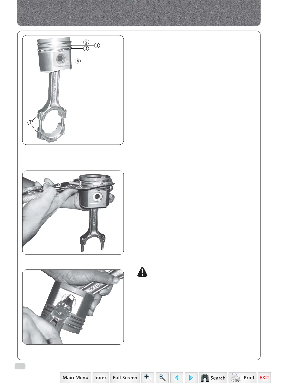
Fig. 3
Connecting Rod & Piston Assembly
Fig. 4
Removing or installing piston pin circlips
Removing or installing piston rings with ring expander
1. Cylinder number
2. Top compression
ring
3. Zud Compression
ring
4. Oil control rings
5. Piston pin snap
ring
c) Check the connecting rods for alignment (Fig.6).
The bores must be square and parallel with each
other in all planes within +0.12 (+0.005 inch)
(L-6) measured 127 mm (5 inches) each side of
the centre line (A-6), if necessary realign by
straightening the connecting rod or replace them.
d) Check the threads in the connecting rod big end
for wear and damage.
e) Check the wear and condition of the connecting
rod bushings. If replacement is necessary proceed
as follows :
1. Press out the old bushing (10-2).
2. Align the oil hole in the new bushing with
the oil hole in the connecting rod and, using
a pilot dolly, press the bushing into the rod.
3. Ream the bushing to the dimension given
in specifications and check the fit of the
piston pin.
f) Check the piston pin for wear or corrosion.
g) If the piston pin is a slack fit in an otherwise
serviceable piston, the piston bore and connecting
rod bushing can be reamed to take an oversize
piston pin. Refer the specifications for dimensions.
h) Insert piston ring in bore and use a piston without
ring to it square in the bore. Check the ring gap
(Fig. 7).
i) Repeat operation (h) with each piston ring and
reject anywhere the gap exceeds. (0.030 inch).
j) Check new rings in the same manner, as detailed
in operation (h) and check the gap to
specifications. The ends of the ring may be filled
carefully to bring the gap within the limits.
k) Check the clearance between the connecting rod
bearings and the crankshaft as follows :-
NOTE: Do not rotate the crankshaft while this check
is being made.
1) Assemble the insert to the connecting rods
and caps.
2) Lay a length of plastigauge across the
bearing cap insert.
3) Install the connecting rod on the crankshaft
all the main rod and tighten bolts to the
correct torque.
4) Remove each bearing cap and measure
thickness of the plastigauge to determine
the bearing clearance.
Remove the connecting rod from the
crankshaft.
Connecting Rods, Pistons & Cylinder Sleeves
 Loading...


