C-36
35 Series 4WD, Model - 3535, 4035, 4535 and 5035 SM June’08
d) Measure and check the clearance with the piston
pin at right angles to the crankshaft axis.
(Refer to “Specifications”)
It should require 2 to 6 lbs. pull to move the
ribbon gauge.
5. INSTALLATION :
a) Immerse the piston assembly in clean engine oil
and fit a ring compressor over the piston.
b) Place the connecting rod in the correct cylinder
and push down steadily on the piston until it is
completely in the cylinder.
c) Wipe the crankshaft bearing end of the rod to
remove and dirt gathered during installation.
Wipe the bearing upper half clean then fit it to
the connecting rod. Apply oil to the bearing
surface and position the connecting rod on the
crankshaft with the number to the F.I. Pump side.
d) Wipe the bearing cap and lower half bearing clean
then assemble together. Apply oil to the bearing
surface and install the cap on the connecting rod
with the number to the F.I. Pump side.
e) Tighten the bolts to the specified torque.
f) Proceed as detailed in ops. (a) to (e) for the
remaining piston assemblies.
NOTE: When correctly positioned, the connecting rod cap
bearing half will stand out 0.7 mm (0.030 in)
above the cap surface and will engage inside
the connecting rod half bore. Failure to position
correctly will result in the bearing halves being
out of line when the bearing cap bolts are
torqued.
g) Install the oil pump.
h) Install the cylinder head.
6. DISMANTLING :
Using a piston ring expander, remove the piston rings
in the following order. First, remove the top compression
ring (Fig 11-2); then remove the second compression
ring (Fig 12-2) and finally remove the third oil control
ring (Fig. 13-2) and the expander. Remove the two
circlips (Fig 6-2) and push out the piston pin (Fig 5-2)
out of the pin boss. The pin can be pushed out by
applying a slight hand pressure. Identify the piston pin
and the piston (Fig 4-2) with a paint mark or a tag.
Do not interchange pins and pistons while assembling.
The connecting rod can be removed and installed
without having to separate the engine from the clutch.
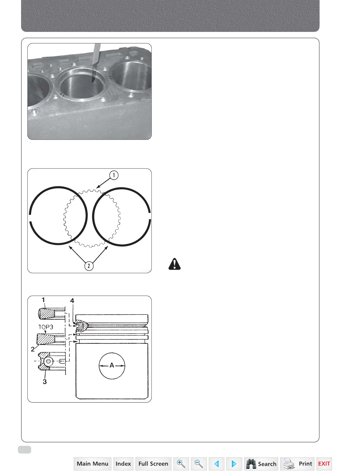
Fig. 7
Fig. 9
Agreement of piston rings (Piston with insert 4)
1. 1st compression ring
2. 2nd compression ring
3. Oil control ring
4. Insert
A. Piston pin
bore nominal
Fig. 8
Connecting Rods, Pistons & Cylinder Sleeves
 Loading...


