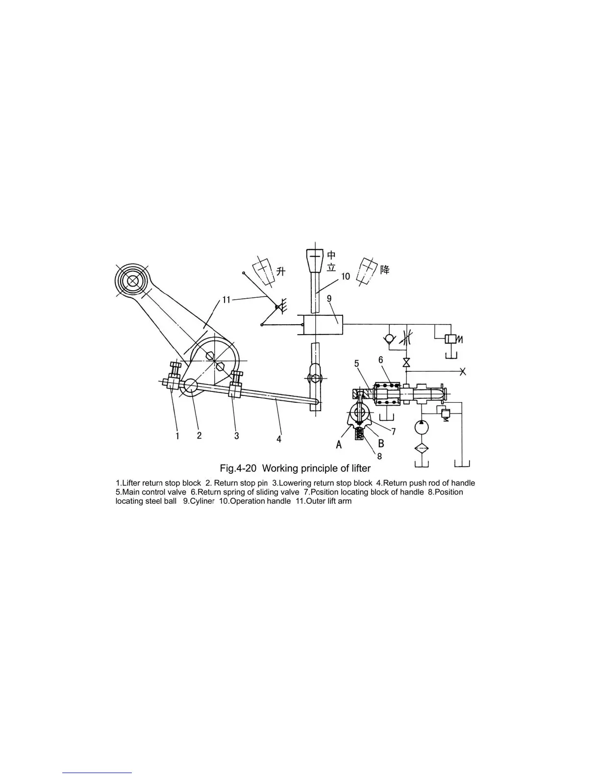
44
tension of return spring (6) of the main control valve, operation handle (10) and main control
valve (5) jump back to the neutral position at the same time. And the cylinder stops returning
oil, the implement also stops falling. Thus, the falling of the implement depends on the fixed
position of lowering return stop block (3) on return push rod (4) i.e. the closer the clearance
between lowering return stop block and operation handle is the lower the implement falls.
Loosen the tightening bolt of lowering return stop block, the return push rod will lose the
ability to make the operation handle return to neutral position. And the main control valve
stops at lowering position from beginning to end, while the cylinder is in "floating" state all
the time.
While raising the implement, push operation handle (10) to lifting position and then
position locating steel ball falls into position locating slot A (Fig.4-20), main control valve (5)
moves left to lifting position. The implement begins to rise; with the implement rising
gradually, meanwhile, return stop pin (2) rotates around the lift shaft clockwise; when the
stop pin slips to contact lifting return stop block (1), drive return push rod (4) to move left,
and at the same time rotates operation handle (10) until pull the locating steel ball (8) out of
its locating slot. In such case, under the action of the tension of return spring (6), operation
handle (10) and main control valve (5) jump to neutral position at the same time. And the oil
pump stops supplying oil to the cylinder, the implement stops rising. The raising height of the
implement depends on the fixed position of the lift return stop block (1) on the return push
 Loading...