45
rod (4). The closer the clearance between return stop block (1) and return push rod (4) is, the
higher the implement rises.
Notes:
During operation, if the adjustment is not suitable, it possibly makes the
operation handle can not return to its position in time, and can cause parts damage due to
overload of hydraulic system.
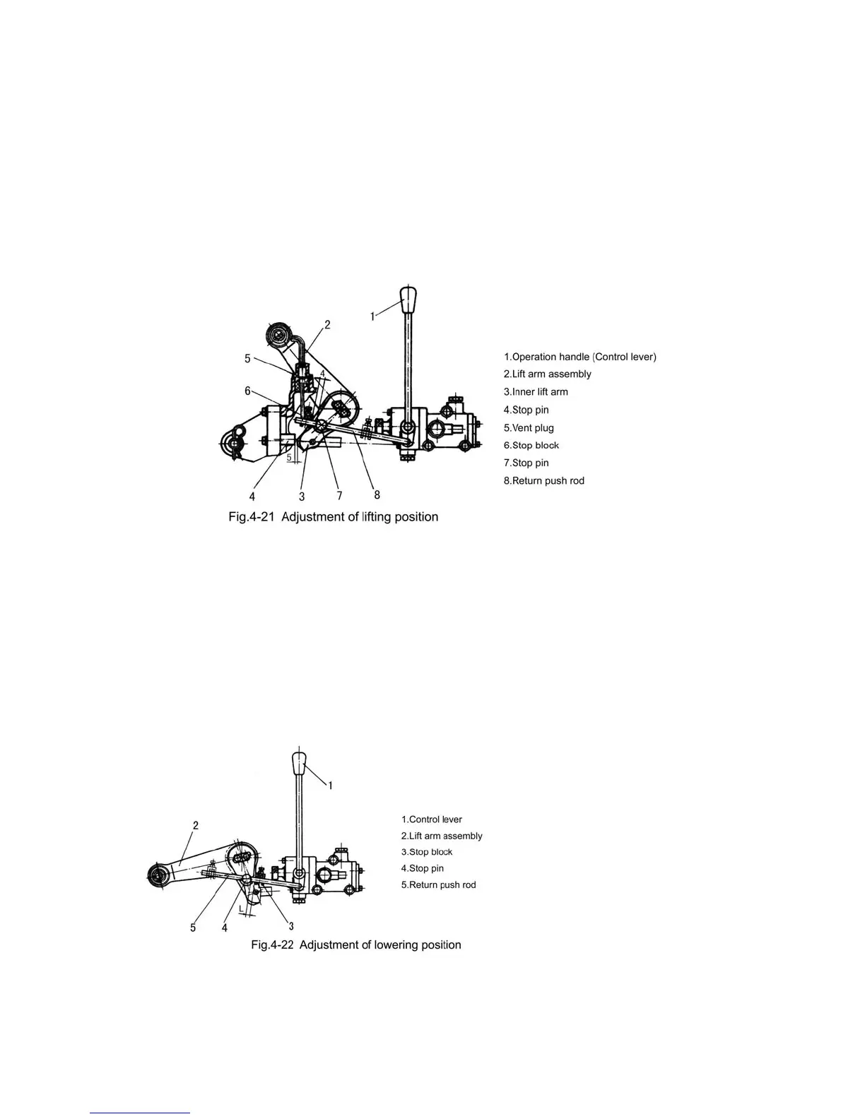
C. Adjustment of hydraulic lifter
①
Adjustment of the utmost lifting position (Fig.4-21)
Set the control lever (1) at the neutral position which is illustrated in Fig.4-21. Rotate the
lift arm assembly (2) upward, until the clearance between the end of inner lift arm (3) and
stop pin (4) is not less than 5mm (insert a steel pad through the hole vent plug (5), control this
clearance by the pad thickness). Adjust the clearance between stop block (6) and stop pin (7)
to be 9-10mm, then fix the stop block on the return push rod (8) with bolt and nut.
②
Adjustment of the lowering position
Set the control lever (1)
at the neutral position, rotate
the lift arm assembly (2)
downwards until the desired
lowering position arrives, and
adjust the clearance L
between stop block (3) and
stop pin (4) to be 9-10mm.
While in position adjusting,
adjustment should be done in
ploughing and forwarding; as the plough lowers into the soil and the required ploughing
 Loading...