Do you have a question about the Main ECO ELITE COMBI 25 and is the answer not in the manual?
Explains the responsibilities and purpose of the Benchmark scheme for installers and customers.
Details how Building Regulations require notification of installations and the role of self-certification schemes.
Lists relevant British Standards and Irish Standards codes of practice for gas and water installations.
Provides general advice on safe manual handling, emphasizing health and safety responsibilities.
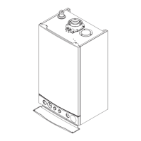
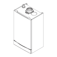
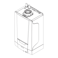
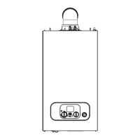
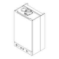
Describes the Main Eco Elite Combi as a fully automatic gas fired wall mounted condensing boiler.
Provides a diagram and numbered list of the main components and their locations within the boiler.
Explains how the boiler operates in central heating mode, including pump circulation and burner control.
Lists detailed technical specifications for both 25 and 30 models, including inputs, outputs, pressures, and dimensions.
Presents detailed performance figures, energy efficiencies, and consumption data for the boiler models.
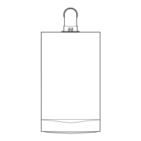
Provides a diagram with dimensions for installation and clearance requirements.
Details requirements for fully pumped SEALED SYSTEMS ONLY and water treatment for corrosion prevention.
Outlines the procedure for filling and pressurising the central heating system, including using a filling loop.
Covers DHW circuit requirements, water regulations, and potential issues like backflow prevention.
Specifies suitable locations for boiler installation, considering flue discharge and frost protection.
Outlines requirements for gas supply installation, pipe size, and connection to the appliance.
Provides extensive guidelines for condensate discharge pipework, including fall, material, insulation, and freezing prevention.
Gives general guidelines for siting balanced flue terminals, including clearances and nuisance prevention.
Explains the suitability of the standard flue for horizontal termination and details maximum equivalent flue lengths.
Guides on safe unpacking, risk assessment, and initial wall preparation for mounting the boiler.
Details the steps for fitting the boiler onto the wall plate, including sealing washers and connection tightening.
Guides on fitting the horizontal telescopic flue, including adjusting sections and securing the terminal assembly.
Continues fitting instructions for the flue, including trims, making good, and terminal guards.
Details how to connect external controls like room thermostats and frost thermostats to the boiler.
Provides a step-by-step guide for commissioning the boiler, including system checks and operational settings.
Details the mandatory combustion check procedure using a flue gas analyser and specific readings.
Explains how to check and set the operational gas inlet pressure and measure the gas rate.
Covers final steps after commissioning, including user instruction, checklist completion, and handover.
Recommends annual servicing by a competent person and lists checks required during routine servicing.
Continues the inspection steps, detailing checks on gas/air inlet, fan, burner assembly, and filters.
Provides instructions for disconnecting, removing, and fitting a new igniter.
Guides on removing and replacing the fan, including examining gaskets and insulation.
Details the procedure for removing and fitting a new burner, checking insulation and gaskets.
Provides instructions for pulling the plug off and removing/refitting the safety thermostat.
Guides on draining the circuit, unscrewing the air vent, and reassembling with a new seal.
Guides on draining the circuit, undoing nuts, and removing/refitting the pressure gauge assembly.
Guides on draining the circuit, removing the gas valve, undoing screws, and withdrawing the heat exchanger.
Guides on noting settings, removing the control box cover, disconnecting plugs, and replacing the PCB.
Details replacing the gas valve, checking CO2, and adjusting the throttle screw.
Explains the process of checking and adjusting the gas valve for correct CO2 levels at maximum and minimum rates.
Provides a detailed wiring diagram showing connections for various components to the control PCB.
Lists basic checks for gas, water, and electrical supplies, as well as preliminary electrical system checks.
Provides a flowchart for troubleshooting central heating operational issues based on error codes and symptoms.
Provides a flowchart for troubleshooting domestic hot water operational issues based on error codes and symptoms.
Provides detailed troubleshooting steps for various fault scenarios and component checks.
| Model | Main ECO ELITE COMBI 25 |
|---|---|
| Category | Boiler |
| Output | 25 kW |
| Efficiency | 93% |
| Flow Rate | 10.2 l/min |
| Fuel Type | Natural Gas |
| Boiler Type | Combi |
| Mounting | Wall-mounted |
| ERP Efficiency | A |
| DHW Output | 25 kW |
| Warranty | 5 years |