16 6 720 607 160
12.4 FITTING A VERTICAL FLUE
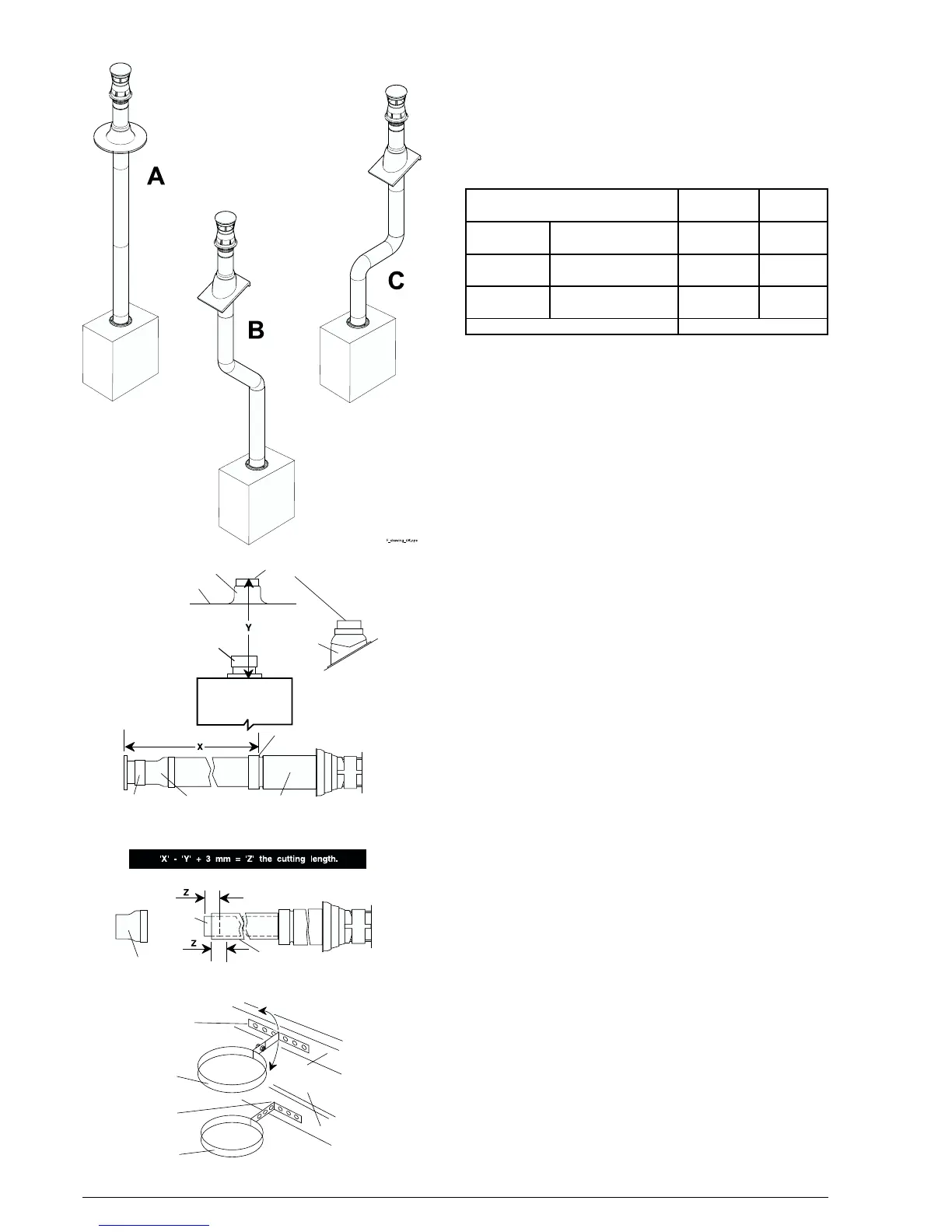
Possible configurations of flue are as per Fig. 17.
Vertical flue kits and flue extension components are detailed
in Section 3, Page 6, Table 2 - Flue Details.
For vertical application the white painted elbow is discarded.
The Maximum and Minimum flue lengths available for vertical
configurations are as per table 12.
Table 12
Fig. 17
Appliance
Adaptor
Terminal
Assembly
Flue Tube
Adaptor
Assembly
Contact Rim Lip
Appliance
Adaptor
Contact Rim
Pitched
Roof
Flashing
Flat Roof Flashing
Roof
Flue Tube
Adaptor
Assembly
Outer
Terminal
Tube
Inner
Terminal
Tube
Fig. 18
12.4.1 Standard Vertical installation:
Secure the flashing kit to the roof.
Refer to Fig. 18.
Measure the distance from the contact rim on the flashing
kit to the flue support ring on top of the boiler.
This is dimension ‘Y’.
Lay the Terminal Assembly flat and loosely connect the Flue
Tube Adaptor Assembly and the Appliance Adaptor.
Measure the overall length from the contact rim lip to the
base of the adaptor.
This is dimension ‘X’.
Subtract dimension ‘Y’ (actual) from ‘X’ (uncut), add 3mm,
this will give the cutting length ‘Z’.
Take the assembly apart and shorten the inner and outer
tubes by dimension ‘Z’. Remove any burrs.
Fit the Appliance Adaptor to the top of the appliance using
3 screws provided.
Slide the Flue Tube Assembly onto the Appliance Adaptor.
From the roof, slide the Terminal Assembly through the
flashing kit.
From the appliance side, position the terminal clamp bracket
and loosely secure to the roof. Fig. 19.
Locate the base of the Terminal Assembly into the Flue Tube
Adaptor Assembly From the roof, ensure the contact rim of
the flashing kit has slid up inside the outer tube of the Terminal
Assembly.
Secure the Terminal Assembly to the Flue Adaptor Assembly
and Flue Adaptor Assembly to the Appliance Adaptor. Drill
(2mm drill) through the pilot holes and secure using the
screws provided.
Fully secure the Terminal clamp bracket.
Tape around both joints to give an air tight seal.
Make good around the flashing kit.
Bracket can
pivot to angle
of roof
Roof or
ceiling
member
Bend bracket
to length
Extension
bracket
(100mm Dia.)
Terminal
support
bracket
(125mm Dia.)
Fig. 19
Flue length Restrictor
Configuration
A
No additional bends
Straight vertical
4.0 m Max Table 10
Configuration
B
2 x 45 degree bends 4.0 m Max Table 10
Configuration
C
2 x 90 degree bend 4.0 m Max Table 10
Vertical configuration
Minimum flue length: 1.4 m Min