5
Tip
※With too many parts contained in this product, please assemble the Drawbot as per the steps
indicated in this instruction to avoid confusion. Pay especially attention to the mark of “O”,”X”.
Make sure you are doing exactly as required by the diagram marked with "O", otherwise the parts
may be broken and the robot may fail to work normally.
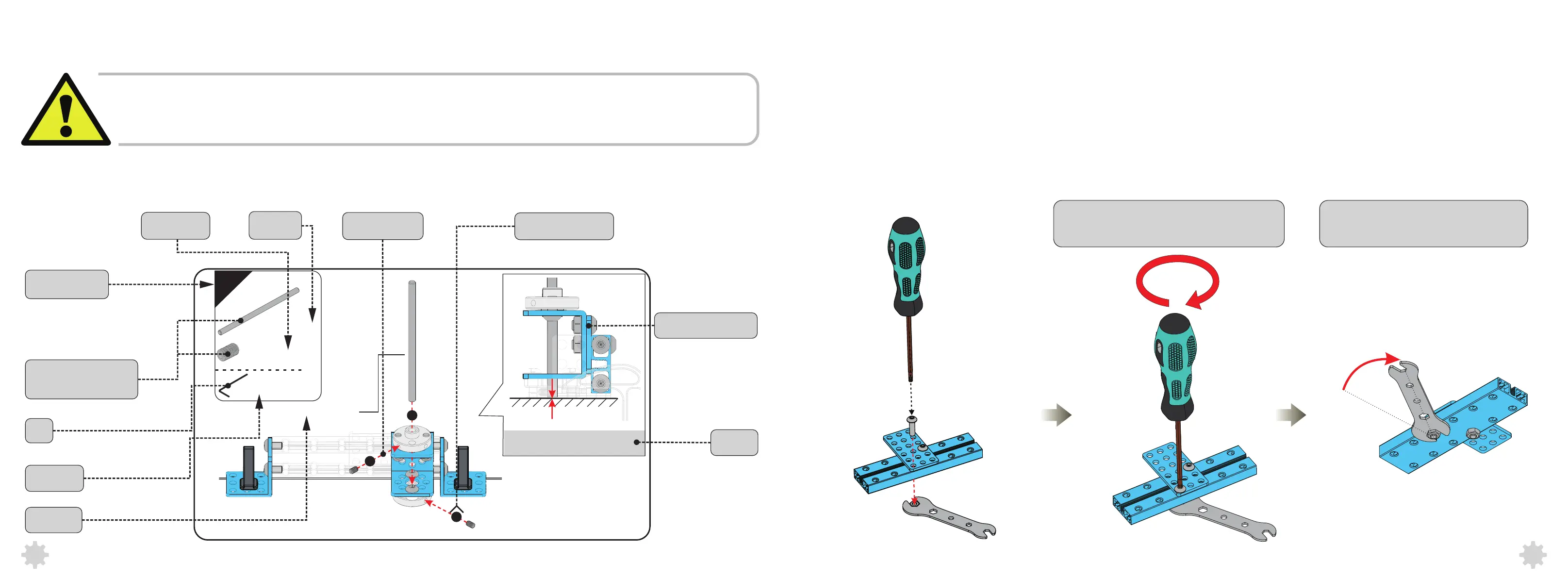
7
(1)
Screw M3×5(2)
1.5mm
Ensure the end of the Shaft is
pushing against the desktop.
Circle Shaft4×80
1
2
3
Diagram
Notes
Assembled Diagram
Assembly Sequence
Assembly Path
Quantity
Parts that are required
in this step
Assembly Step
Part Name
Part Number
Tool
Tool Model
4
1.Make sure to tighten the screw and the nut.
Assembly Requirement
Please assemble the robot in strict accordance with the following three requirements,
Otherwise it will result in inaccuracy or unsatisfying performance.
01.Tighten the screw with force according
to the direction of the diagram
02.Tighten the nut with force according
to the direction of the diagram