Do you have a question about the Makita 3710 and is the answer not in the manual?
Details power requirements and electrical safety for single-phase AC supply.
Guidelines for safe electrical connections, cord usage, and avoiding shock hazards.
Advice on staying alert, using PPE, and preventing accidental starts.
Guidelines for proper operation, maintenance, and avoiding misuse of the power tool.
Information on qualified repair persons and using identical replacement parts for maintenance.
Steps for safely inserting and removing the cutting bit using wrenches.
Guidance on proper feed rates and making sample cuts for best results.
Using the templet guide for cutting along patterns or templates.
Using the straight guide assembly for cutting circles of various radii.
Steps for installing and adjusting the trimmer guide for curved cuts.
Procedure for checking and replacing worn carbon brushes.
This document provides a comprehensive guide for the Makita Trimmer, Model 3710, covering its functional description, usage, and maintenance. It emphasizes safety precautions throughout, urging users to read and understand all instructions before operation and to save them for future reference.
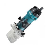
The Makita Trimmer, Model 3710, is a double-insulated power tool designed for flush trimming and profiling of wood, plastic, and similar materials. Its core function revolves around a rotating bit that can be adjusted for protrusion and angle to achieve various cutting effects.
The tool features a base, a clamping nut, a scale, and an adjusting screw for precise control over the bit's protrusion. By loosening the clamping nut and turning the adjusting screw, the bit can be moved up or down, and then secured firmly in place.
For angled cuts, the tool base itself can be adjusted. Loosening the wing bolts allows the user to set the base at desired angles, marked by 5° graduations, to achieve specific cutting angles.
When chamfering, the trimmer shoe can be adjusted to control the amount of chamfer. This involves loosening wing nuts and manipulating the trimmer shoe. A crucial safety note here is to ensure the tool is unplugged and the switch is in the "OFF" position, then rotate the collet nut to confirm the bit turns freely without contacting the base or trimmer shoe.
The tool is operated via a switch lever, moving it to the "I" (ON) position to start and to the "O" (OFF) position to stop.
Before any adjustments or work, it is paramount to ensure the tool is switched off and unplugged.
To install a trimmer bit, insert it all the way into the collet cone and securely tighten the collet nut using the two provided wrenches. It's important not to tighten the collet nut without a bit inserted, as this can damage the collet cone. Removal is the reverse of the installation process.
The trimmer shoe is factory-installed. If it needs to be reinstalled after removal, use the bolts, wing nuts, spring washers, and flat washers as illustrated in the manual.
To begin cutting, turn the tool on and allow the bit to reach full speed before making contact with the workpiece. Move the tool over the workpiece surface, keeping the tool base and trimmer shoe flush with the sides of the workpiece. The tool can also be used as a conventional trimmer by removing the trimmer shoe. When performing edge cutting, the workpiece surface should be positioned on the left side of the bit in the feed direction.
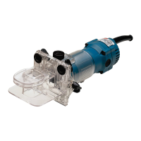
The templet guide allows the trimmer to be used with templet patterns. To install it, first remove the tool base, loosen the wing bolts, and secure the tool base horizontally. Then, loosen the two screws on the tool base. Place the templet guide on the tool base, aligning two of its four convex portions with the two screws, and secure it. Finally, reinstall the tool base on the tool.
To use the templet guide, secure the templet to the workpiece. Place the tool on the templet and move it, allowing the templet guide to slide along the templet's side. Note that the workpiece will be cut slightly differently from the templet due to the distance (X) between the router bit and the outside of the templet guide. This distance can be calculated using the formula: (outside diameter of the templet guide - router bit diameter) / 2.
The straight guide is attached to the guide plate with a bolt and wing nut. It is secured to the tool base using a clamp screw, wing nut, and wing bolt.
Circular work can be achieved by assembling the straight guide and guide plate as shown in the figures. The minimum radius for circles to be cut is 70 mm, and the maximum is 221 mm (distance between the center of the circle and the center of the bit). For circles between 70 mm and 121 mm, the straight guide is used. For circles between 121 mm and 221 mm, a different setup is used, though circles between 172 mm and 186 mm cannot be cut with this guide. To cut a circle, align the center hole in the straight guide with the desired center of the circle, drive a nail (less than 6 mm in diameter) into the center hole to secure the straight guide, and pivot the tool clockwise around the nail.
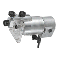
The trimmer guide facilitates trimming and curved cuts in veneers. It is installed by loosening the wing bolts, securing the tool base horizontally, and attaching the trimmer guide with clamp screw (A). The distance between the bit and the trimmer guide is adjusted by loosening clamp screw (B) and turning the adjusting screw (1 mm per turn), then tightening clamp screw (B) to secure it. When cutting with the trimmer guide, move the tool with the guide roller riding the side of the workpiece.
Before performing any inspection or maintenance, always ensure the tool is switched off and unplugged.
Regularly remove and check the carbon brushes. Replace them when they wear down to the limit mark. Keep the carbon brushes clean and ensure they can slip freely in their holders. Both carbon brushes should be replaced simultaneously with identical carbon brushes. To replace them, use a screwdriver to remove the brush holder caps, take out the worn brushes, insert new ones, and secure the caps.
For maintaining the product's safety and reliability, all repairs, maintenance, or adjustments should be performed by Makita Authorized Service Centers, using only genuine Makita replacement parts.
| Toolholder | 6 mm |
|---|---|
| Input power | 530 W |
| Product color | Black, Blue |
| Vibration emission | 1.5 m/s² |
| Weight | 1600 g |
|---|