Do you have a question about the Makita 3711 and is the answer not in the manual?
General safety guidelines applicable to all power tools for safe operation and injury prevention.
Ensuring a safe working environment by maintaining cleanliness, avoiding hazards, and keeping others away.
Guidelines for safe use of electrical power tools, including plug and cord safety, and protection against water.
Measures to ensure operator safety, including alertness, protective equipment, and proper handling.
Precautions for handling trimmer bits, checking for damage, and safe operational practices.
Guidelines for safe power tool operation, maintenance, and awareness of chemical hazards.
Instructions for proper use, maintenance, and handling of power tools to ensure safety and performance.
Guidance on servicing the power tool through qualified personnel and using genuine replacement parts.
Procedure for adjusting the bit protrusion by loosening the clamping screw and turning the adjusting screw.
Instructions on how to start and stop the tool using the switch lever.
Overview of the tool's electronic functions, including the indication lamp and unintentional restart proof.
Explanation of the soft-start feature that minimizes start-up shock for smoother operation.
Steps for securely installing or removing trimmer bits using the provided collet nut and wrenches.
Steps for setting up the base, starting the tool, and moving it over the workpiece for cutting.
Guidance on positioning the workpiece for edge cutting with the trimmer bit.
Instructions for using the templet guide to achieve precise cuts with templet patterns.
Steps for attaching the guide plate, adjusting its position, and securing it for straight cuts.
Guidance on moving the tool with the straight guide flush against the workpiece for cutting.
Instructions for attaching the trimmer guide and adjusting its distance from the trimmer bit.
Guidance on moving the tool with the guide roller riding the side of the workpiece for curved cuts.
Procedure for checking and replacing worn carbon brushes to maintain tool performance.
Information on recommended trimmer bits, including straight, V-grooving, and drill point flush trimming bits.
Details on chamfering, corner rounding, and cove beading bits for various woodworking applications.
Specifications for ball bearing flush trimming, chamfering, corner rounding, and beading bits.
Details on ball bearing cove beading and roman ogee bits for specialized edge treatments.
This document is an instruction manual for the Makita Trimmer model 3711. It provides specifications, safety warnings, functional descriptions, assembly instructions, operation guidelines, and maintenance information for the tool.
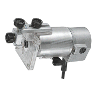
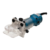
The Makita Trimmer 3711 is a power tool designed for trimming the edge of laminate sheets or similar materials. It features double insulation for enhanced safety and is intended for use with single-phase AC supply.
To adjust the bit protrusion, the clamping screw needs to be loosened, and the base moved up or down by turning the adjusting screw. After adjustment, the clamping screw must be tightened firmly to secure the base.
The tool is started by moving the switch lever to the "I" position and stopped by moving it to the "O" position. Users are cautioned to ensure the tool is switched off before plugging it in.
The trimmer is equipped with electronic functions for easy operation, including an indication lamp and unintentional restart proof.
The trimmer bit is inserted all the way into the collet cone, and the collet nut is tightened securely with the two wrenches provided. To remove the bit, the process is reversed. Users are warned not to tighten the collet nut without a bit inserted, as this can break the collet cone, and to use only the provided wrenches.
When operating, the tool should be held firmly with one hand on the housing, avoiding contact with metal parts. The base is set on the workpiece without the bit touching, the tool is turned on, and allowed to reach full speed before being moved forward smoothly over the workpiece surface. The feed rate is crucial; moving too fast can result in poor cut quality or damage, while moving too slowly can burn the cut. A sample cut on scrap lumber is recommended to determine the proper feed rate and check dimensions. For edge cutting, the workpiece surface should be on the left side of the trimmer bit in the feed direction.
The templet guide allows the trimmer to be used with templet patterns. To use it, the clamping screw is loosened, the guide holder and chip deflector are removed, and the templet guide is placed on the base, then secured with the base protector and screws. The tool is then moved with the templet guide sliding along the side of the templet. The workpiece will be cut slightly differently from the templet, and the distance (X) can be calculated using the formula: (outside diameter of the templet guide - trimmer bit diameter) / 2.
The straight guide is used for straight cuts when chamfering. The guide plate is attached to the straight guide with a bolt and wing nut. The guide holder and chip deflector are removed, and the straight guide is attached with the clamping screw. The distance between the trimmer bit and the straight guide is adjusted by loosening the wing nut, and then tightened securely. When cutting, the tool is moved with the straight guide flush with the side of the workpiece.
The trimmer guide facilitates curved cuts in veneers. The guide roller rides the curve, ensuring a fine cut. The chip deflector is attached to the groove of the base, and the trimmer guide and guide holder are installed with the clamping screw (A). The distance between the trimmer bit and the trimmer guide is adjusted by turning the adjusting screw (1 mm per turn), and then the clamping screw (B) is tightened. When cutting, the tool is moved with the guide roller riding the side of the workpiece.
Before any inspection or maintenance, the tool must be switched off and unplugged. Users are warned against using gasoline, benzine, thinner, alcohol, or similar substances, as they can cause discoloration, deformation, or cracks. All repairs, maintenance, or adjustments should be performed by Makita Authorized or Factory Service Centers using Makita replacement parts to maintain product safety and reliability.
Carbon brushes should be checked regularly and replaced when they wear down to the limit mark. Both brushes must be replaced at the same time with identical carbon brushes. To replace them, a screwdriver is used to remove the brush holder caps, the worn brushes are taken out, new ones are inserted, and the caps are secured.
The manual lists various optional accessories, including different types of trimmer bits (straight bit, U-grooving bit, V-grooving bit, drill point flush trimming bit, drill point double flush trimming bit, chamfering bit, corner rounding bit, cove beading bit, ball bearing flush trimming bit, ball bearing chamfering bit, ball bearing corner rounding bit, ball bearing beading bit, and ball bearing roman ogee bit). Users are cautioned to use only accessories or attachments recommended by Makita for this specific tool, as using others may pose a risk of injury. For assistance or more details, users should contact their local Makita Service Center. Some items may be included as standard accessories and may vary by country.