October 2015
2.2.3.2. ASSEMBLING
Assemble by reversing the disassembly procedure.
2.2.4. SPEED CHANGE LEVER ASS’Y
2.2.4.1. ASSEMBLING
Assemble by reversing the disassembly procedure.
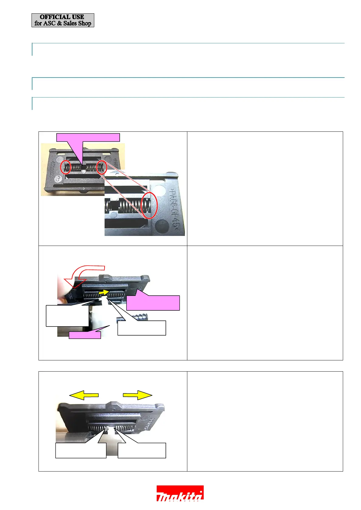
1. A
ssemble Compression spring 4 (x2) as drawn.
Note:
Hook one roll of the spring to the notches of Speed
change lever.
2. Fit Pin on the lever of Speed change lever into
Compression spring 4 while pushing Speed change lever
ass’y in the direction of the arrow
.
P
ush Compression spring 4 with projection of Speed
Note:
Hook one roll of the spring to the notches of Speed
change lever.
3.
Shift Speed change lever in the either direction.
Compression spring 4 (x2)
change lever
of Speed change
lever
ass’y
Speed change lever
Speed change ever
14 / 18

 Loading...