8 ENGLISH
Function Status of the tool Status of the LED indicator/beeper Action to be taken
LED indicator Beeper
Alarm for low battery
capacity
The battery power
became low and it is
time to replace the
battery cartridge.
Flickers in red slowly. A series of long beeps Replace the battery with
fully charged one.
Auto-stop with low
remaining battery
capacity
The battery power is
almost used up and the
tool stopped.
Lights up in red. A long beep Replace the battery with
fully charged one.
Anti-reset of controller The battery voltage
dropped abnormally for
some reason, and the
tool stopped.
Flickers in red and green
alternatively.
A series of short beeps Replace the battery with
fully charged one.
Overheat protection Tool's controller heated
up abnormally and the
tool stopped.
Flickers in red quickly. A series of short beeps Remove the battery car-
tridge immediately and
cool the tool down.
Motor failure detection Motor failure has been
detected. At this time,
tool does not work.
Flickers in red and green
alternatively.
A series of short beeps Ask your local Makita
Service Center for repair.
Maintenance alarm A maintenance time has
come according to your
preset number of screws
driven.
Flickers in yellow. – Reset the alarm with the
application software.
Alarm for unavailable
data communication
(with the tool in connec-
tion with PC)
Data cannot be
exchanged between the
tool and PC in spite of
the connection.
Flickers in yellow. – Restart the application
software and re-connect
the USB cable.
Indication that data com-
munication is available
(with the tool in connec-
tion with PC)
The tool is connected to
PC and data communi-
cation is available.
Flickers in green. – –
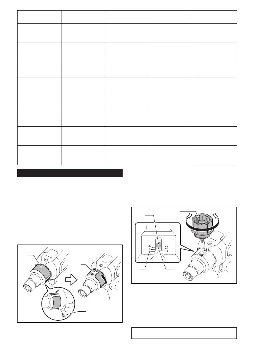
Adjusting the fastening torque
When you wish to drive machine screws, hex bolts,
etc. with the predetermined torque, adjust the fastening
torque as follows.
1. First remove the battery cartridge from the tool.
2. Loosen and remove the screw that secures ring.
3. Rotate the ring in the front of the tool by hand so
that a hole can be seen below the ring.
4. Install the battery cartridge in place. Pull the
switch trigger and release it so that the adjust ring
rotates and the hole becomes visible. And then remove
the battery cartridge.
3
1
2
►1. Ring 2. Screw 3. Hole
5. Use an optional adjust grip to adjust the fastening
torque. Insert the pin of the adjust grip into the hole
in the front of the tool. And then, turn the adjust grip
clockwise to set a greater fastening torque, and coun-
terclockwise to set a smaller fastening torque.
6. Align the yellow line with your desired number on
the fastening torque scale.
1
3
2
4
►1. Adjust grip 2. Hole for adjust grip 3. Scale
4. Yellow line
7. Insert the battery cartridge and be sure that a
fastening torque has been set up by using a fastening
torque tester.
8. Rotate the ring in front of the tool and then tighten
the screw to secure the ring.
NOTE: Numbers on the fastening torque scale is a
guideline to set up your desired fastening torque.

 Loading...