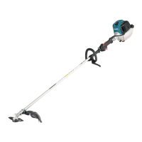
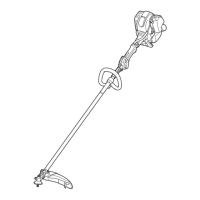
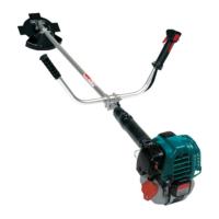
EasyManua.ls Logo

Makita EM2600U User Manual

Makita EM2600U
76 pages
To Next Page IconTo Next Page
Page #1 background imageLoading...
Page #1 background image
Owners and Safety Manual
for Brush Cutter/String Trimmer
Manuel d’emploi et de sécurité
de la Débroussailleuse Thermique
Manual de empleo y de seguridad
para Desbrozadora
EM2600U EM2600L
Important:
Read this instruction manual carefully before putting the brush cutter/string trimmer into operation and strictly observe the safety regulations!
Preserve instruction manual carefully!
Important :
Lisez attentivement ce manuel d’instructions avant de vous servir de la débroussailleuse thermique pour la première fois, et respectez à la
lettre les consignes de sécurité!
Conservez précieusement ce manuel d’instructions!
Importante:
Lea esta manual de instrucciones con atención antes de utilizar la desbrozadora y ¡observe estrictamente las regulaciones de seguridad!
¡Conserve cuidadosamente su manual de instrucciones!

Other manuals for Makita EM2600U

Questions and Answers:

Makita EM2600U Specifications

General IconGeneral
Engine power1.1 hp
Number of strokes2
Sound power level112 dB
Fuel tank capacity0.6 L
Vibration emission14.7 m/s²
Engine displacement25.7 cm³
Sound pressure level96.15 dB
Sound power level guaranteed2.5 dB
Power sourceGasoline
Weight and Dimensions IconWeight and Dimensions
Depth410 mm
Width610 mm
Length1770 mm
Weight5000 g

Summary

Safety Instructions

General Operating Instructions

Read and understand manual for correct operation. Use with care and attention.

Intended Use of Equipment

Only for cutting grass, weeds, bush, undergrowth. Not for edging or hedge cutting.

Personal Protective Equipment

Wear appropriate clothing, helmet, goggles, hearing protection, gloves, and sturdy shoes.

Residual Risks

Hazards include lung damage, hearing damage, and health issues from vibration.

Starting the Brush Cutter

Ensure safe area, check tool security, lever operation, and handles. Ensure safe footing.

Refuelling Safety Precautions

Switch off engine, keep away from flames, no smoking. Avoid fuel/oil skin contact. Clean spills immediately.

Method of Operation

Operate in good light, ensure safe footing. Never cut above waist height or on unstable surfaces.

Kickback (Blade Thrust)

Uncontrolled kickbacks may occur, especially using the 12 to 2 o'clock blade section.

Kickback Prevention

Avoid 12 to 2 o'clock section. Use 8 to 11 o'clock section for best results and minimal kickback.

Cutting Tools

Use nylon heads for grass, metal blades for weeds/grass/bushes. Avoid chains or flail blades.

Maintenance Instructions

Service by authorized center with genuine parts. Check cutter, guards, strap, and blades before use.

First Aid Procedures

Ensure first-aid box availability. Provide accident details: place, what happened, number injured, injuries, name.

Vibration Effects and Precautions

May affect circulation. Symptoms: numbness, tingling, pain. Consult physician if symptoms occur.

Mounting the Handle

U Handle Model Mounting

Place handles on holder, control lever right. Adjust angle and tighten bolts.

Throttle Cable Positioning

Route cable to control lever, insert into slot, ensure correct positioning for smooth operation.

Loop Handle Model Mounting

Thread handle holder onto tube, fix assistant handle, tighten bolts.

Mounting the Protector

Protector Installation for Metal Blades

Fix the protector to the clamp using specified bolts.

Protector Installation for String Head

Fit string head protector into main protector, tighten with nuts and screws.

Mounting Cutter Blade and Nylon Head

Cutter Blade Mounting

Mount blade, fit receiver washer, clamp washer, secure with nut/spring washer. Torque: 13-23 N-m.

Nylon Cutting Head Mounting

Screw nylon head onto shaft. Ensure counterclockwise rotation.

Fuel and Refuelling

Fuel Handling Precautions

Handle fuel with care in ventilated areas. Avoid vapor inhalation and skin/eye contact.

Fuel and Oil Mixture

Use unleaded fuel (min. octane 91). Use 50:1 ratio for two-stroke oil (JASO FC or ISO EGD).

Correct Mixture Ratio

Mix half fuel with oil, then add remaining fuel. Shake well before use.

Refuelling Procedure

Switch off engine. Clean fuel cap area. Fill tank, tighten cap, clean cap and tank.

Fuel Storage

Store fuel in approved containers, away from children. Purchase only quantity for 4-week period.

Correct Handling

Shoulder Strap Attachment

Adjust strap length so cutter blade is parallel to the ground.

Equipment Detachment

In emergency, push notches to detach. Maintain control to avoid deflection and injury.

Important Operating Points and Stopping

Starting Procedure

Move 3m from refuelling. Place on clean ground, away from objects. Tool rotates immediately.

Cold Start for U Handle Models

Set I-Stop Switch to on. Grasp handle, press throttle, press lock button, release lever.

Cold Start for Loop Handle Models

Set Start-Stop Switch to start. Grasp handle, press throttle, set switch to start, release lever.

Warm Start for U Handle Models

Set I-Stop Switch to on.

Warm Start for Loop Handle Models

Set Start-Stop Switch to neutral. Press primer pump, close choke lever.

Loop Handle Start Procedure Details

Use primer pump, choke lever, starter rope. Manage choke and throttle for correct operation.

Stopping the Engine

Release throttle, push I-Stop/Start-Stop Switch to STOP. Allow cutting head to stop by itself.

Caution During Operation

Operating Speed and RPM Management

Avoid high no-load RPM. Reduce revolutions when not in use to preserve lifespan.

Resharpening Cutting Tools

Professional Resharpening

Cutting tools must be resharpened by an authorized facility to avoid imbalance and damage.

Nylon Cutting Head Operation

Nylon Head Operation

Feeds cord via bump & feed. Tap head at 6000 min-¹ to feed cord.

Replacing Nylon Cord

Stop engine. Remove spool, hook new cord, wind around spool, feed through eyelets.

Servicing Instructions

Daily Inspection and Maintenance

Check for loose parts, clogged cooling passages. Check blade/head mounting. Check I-Stop switch function.

Cleaning the Air Cleaner

Turn choke to closed, keep carburetor clean. Remove, wash sponge element in lukewarm water, dry, and replace.

Checking the Spark Plug

Use universal wrench. Gap: 0.6-0.7 mm. Clean or replace if dirty or worn.

Greasing the Gear Case

Supply grease to gear case through grease hole every 30 hours.

Fuel Tank Suction Head Maintenance

Inspect fuel filter periodically. Replace if hardened, dirty, or clogged. Replace quarterly for proper fuel supply.

Storage Instructions

Long-Term Storage Procedure

Drain fuel from tank/carburetor. Add oil to cylinder, clean engine, wipe with oil cloth, store dry.

Troubleshooting Guide

Engine Starting Issues

Check ignition, fuel supply, compression, mechanical faults. Check switches and spark plug.

Warm Start Problems

Check fuel supply, starter engagement, tank fill. Clean carburetor if contaminated.

Engine Stalling Issues

Check fuel supply, tank fill, ignition spark. Address idling, carb, or fuel line issues.

Insufficient Performance

Check fuel tank vent, supply line, cable, or I-Stop switch. Inspect air filter, carb, muffler, exhaust.

California Emissions Control Warranty

Manufacturer's Warranty Coverage

Emissions system warranted for two years. Parts repaired/replaced by Makita USA, Inc.

Owner's Warranty Responsibilities

Perform required maintenance, retain receipts. Avoid abuse, neglect, improper maintenance, or unapproved modifications.

Defects Warranty Requirements

Warranty begins on delivery date. Parts free from defects for two years. Repair/replacement covered.

Emissions Warranty Parts List

Lists parts: Fuel Metering, Air Induction, Ignition Systems, Miscellaneous Items, Evaporative Emission Components.

Maintenance Statements

Perform scheduled maintenance. Retain proof of services. Failure to maintain may void warranty.

Maintenance Procedures and Intervals

Daily Maintenance Procedures

Clean engine, check bolts, air filter, spark plug, muffler outlet.

Monthly Maintenance Procedures

Check muffler outlet, fuel filter, adjust valve clearance (if applicable).

Yearly Maintenance Procedures

Replace fuel lines, clean engine, replace worn parts, packings/gaskets.

Federal Emission Component Warranty

Warranty Coverage Details

Applies in all States except CA. Engine conforms to EPA regulations, free of defects.

Warranty Period

Begins on sale date and continues for 2 years.

Covered Parts

Lists parts: Fuel Metering, Air Induction, Ignition Systems, Misc. Items, Evaporative Emission Components.

Obtaining Warranty Service

Take engine to authorized Makita center. Bring sales receipts for diagnosis, repair, or replacement.

What is Not Covered by Warranty

Excludes tampering, misuse, improper adjustment, accident, wrong fuel/oil, non-authorized parts.

Owner's Warranty Responsibilities

Responsible for maintenance, retain receipts. Makita may deny warranty for abuse, neglect, or improper maintenance.

Emission Control System Warranty Information

Keep maintenance records. Warranty repairs must be by authorized center. Use equivalent parts.

Maintenance and Repairs for Warranty

Keep receipts. Warranty repairs must be by authorized center. Use equivalent parts for maintenance.

How to Make a Warranty Claim

All repairs by authorized MAKITA dealer. Notify MAKITA for defective emission-related parts.

Related product manuals