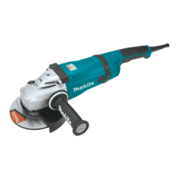
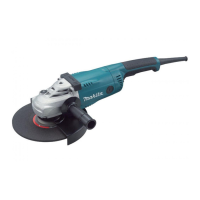
This document provides instructions for the Makita Angle Grinder models GA7070, GA7071, GA9070, and GA9071. It covers the device's function, technical specifications, usage, and maintenance.
The Makita Angle Grinder is designed for grinding, sanding, and cutting metal and stone materials without the use of water. It operates on a single-phase AC power supply with double insulation, allowing use from sockets without an earth wire.
Technical Specifications:
The models vary primarily in wheel diameter and rated speed.
- Wheel diameter: 180mm for GA7070 and GA7071; 230mm for GA9070 and GA9071.
- Max. wheel thickness: 7.2mm for 180mm models; 6.5mm for 230mm models.
- Spindle thread: M14 or 5/8″ (country specific).
- Rated speed (n): 8,500 min⁻¹ for 180mm models; 6,600 min⁻¹ for 230mm models.
- Overall length: 506mm for all models.
- Switch handle type: Bar type for GA7070 and GA9070; D type for GA7071 and GA9071.
- Net weight: Ranges from 6.1 - 6.6 kg for GA7070, 6.2 - 6.7 kg for GA7071, 6.3 - 8.5 kg for GA9070, and 6.4 - 8.5 kg for GA9071.
- Safety class: /II for all models.
The typical A-weighted noise levels are provided, with sound pressure levels (LpA) ranging from 91 dB(A) to 92 dB(A) and sound power levels (LWA) from 102 dB(A) to 103 dB(A), with an uncertainty (K) of 3 dB(A). Users are warned to wear ear protection.
Vibration total values (tri-axial vector sum) are also detailed. For surface grinding with a normal side grip, vibration emission (ah,AG) ranges from 4.9 m/s² to 6.4 m/s². With an anti-vibration side grip, it ranges from 4.8 m/s² to 6.0 m/s². For disc sanding with a normal side grip, vibration emission (ah,DS) ranges from 2.5 m/s² to 4.6 m/s². With an anti-vibration side grip, it ranges from 2.6 m/s² to 4.6 m/s². An uncertainty (K) of 1.5 m/s² applies to all vibration measurements. Users are advised that actual noise and vibration emissions may vary depending on usage and workpiece.
Function Description:
The angle grinder features a shaft lock to prevent spindle rotation during accessory installation or removal. It's crucial not to activate the shaft lock while the spindle is moving to avoid damage.
The switch handle can be rotated 90° left or right to suit work needs. This involves unplugging the tool, pressing the lock button, and rotating the handle until it locks.
The tool incorporates different switch actions depending on the country:
- Lock-on switch: Allows the switch trigger to be locked in the "ON" position for continuous operation. To start, pull the trigger. For continuous operation, pull the trigger and push the lock lever. To stop from the locked position, pull the trigger fully, then release.
- Lock-off switch: A lock lever prevents accidental trigger pulling. To start, push the lock lever, then pull the trigger. Release the trigger to stop.
- Lock-on and lock-off switch: Combines features of both, allowing for continuous operation and preventing accidental starts.
An indication lamp lights up green when the tool is plugged in. It can indicate power cord or controller defects (if it doesn't light up), or controller/switch defects (if it lights up but the tool doesn't start). A red blinking light indicates worn carbon brushes or a defective motor.
The tool includes an unintentional restart proof feature, preventing it from starting if the switch is locked "ON" when plugged in. The indication lamp blinks red to signal this. To cancel, return the switch to "OFF".
Active Feedback Sensing Technology electronically detects situations where the wheel or accessory may bind, automatically shutting off power to prevent further spindle rotation (though it doesn't prevent kickback). The indication lamp blinks red when this technology is active. To restart, turn the tool off, remove the cause of the speed drop, then turn it on.
A soft start feature reduces the starting reaction, ensuring smoother operation.
Usage Features (Assembly and Operation):
Assembly: Always ensure the tool is switched off and unplugged before any assembly work.
- Side grip (handle) installation: The side grip can be installed in any of the three available holes and must be securely tightened.
- Loop handle installation (optional accessory): Provides a more comfortable grip. It is mounted with two bolts that must be securely tightened. The gripping area should be held, keeping hands away from metal parts during operation.
- Wheel guard installation:
- For depressed center wheels, flap discs, flex wheels, or wire wheel brushes, the guard's closed side must always face the operator.
- For abrasive cut-off / diamond wheels, a special guard designed for cut-off wheels must be used. In some European countries, the ordinary guard may be used for diamond wheels, following local regulations.
- Locking screw type: Mount the guard by aligning protrusions with bearing box notches, then rotate to the desired angle and tighten the screw.
- Clamp lever type (optional accessory): Loosen the nut, pull the lever, mount the guard, rotate to the desired angle, then tighten the nut with a spanner and close the lever. Adjust nut tightness if the lever is too tight or loose.
- Depressed center wheel or flap disc installation (optional accessory): Mount the inner flange onto the spindle, ensuring its dented part fits the straight part at the bottom of the spindle. Place the wheel/disc on the inner flange and screw the lock nut with its protrusion facing downward. Tighten the lock nut securely using the shaft lock and a lock nut wrench.
- Flex wheel installation (optional accessory): Follow the instructions for depressed center wheels, but also use a back-up pad over the wheel. Always use the supplied guard.
- Ezynut installation (optional accessory, M14 spindle thread only): Mount the inner flange, abrasive wheel, and Ezynut onto the spindle with the Makita logo facing outwards. Press the shaft lock and tighten the Ezynut by turning the abrasive wheel clockwise. To loosen, turn the outer ring counterclockwise. If the arrow points to the notch, it can be loosened by hand; otherwise, use a lock nut wrench.
- Abrasive disc installation (optional accessory): Mount the rubber pad onto the spindle, fit the disc, and screw the sanding lock nut. Hold the spindle with the shaft lock and tighten the lock nut clockwise with a lock nut wrench.
- Abrasive cut-off / diamond wheel installation (optional accessory): Mount the inner flange onto the spindle, fit the wheel/disc, and screw the lock nut. For Australia and New Zealand, specific outer and inner flanges (78) are used. Never use cut-off wheels for side grinding.
- Wire cup brush installation (optional accessory): Remove other accessories, thread the wire cup brush onto the spindle, and tighten with a wrench. Do not use damaged or unbalanced brushes.
- Wire wheel brush installation (optional accessory): Remove other accessories, thread the wire wheel brush onto the spindle, and tighten with a wrench. Always use a guard that fits the wheel's diameter.
- Dust collecting wheel guard installation:
- For grinding: Mount the guard for grinding flat concrete with a cup-type diamond wheel. It is not for grinding stones or other purposes.
- For cut-off (GA9070 / GA9071): Refer to the dust collecting cover manual for installation.
- Connecting a vacuum cleaner (optional accessory): Use a dust collecting wheel guard and a vacuum cleaner for masonry cutting. Never vacuum metal particles as they can be hot enough to ignite dust and filters.
Operation:
- Grinding and sanding: Turn the tool on, then apply the wheel or disc to the workpiece. Maintain an angle of about 15° to the workpiece surface. During the break-in period with a new wheel, avoid moving the grinder forward to prevent cutting into the workpiece. Once the wheel edge is rounded, it can be used in both forward and backward directions.
- Abrasive cut-off / diamond wheel: Do not "jam" the wheel or apply excessive pressure. Do not attempt excessive depth of cut. Never change the wheel angle during cutting. A diamond wheel must be operated perpendicular to the material.
- Wire cup brush / wire wheel brush: Check operation by running the tool with no load, ensuring no one is in front or in line with the brush. Avoid applying too much pressure to prevent over-bending of wires, which can lead to premature breakage.
Maintenance:
Always ensure the tool is switched off and unplugged before inspection or maintenance.
- Cleaning air vents: Regularly clean the tool's air vents to prevent obstruction.
- Brake maintenance: The tool should be repaired by a Makita Authorized or Factory Service Center if braking performance declines noticeably or if the accessory's inertial rotation continues for more than 6 seconds after releasing the switch trigger.
- Never use gasoline, benzine, thinner, alcohol, or similar substances, as they can cause discoloration, deformation, or cracks.
- Repairs and adjustments should only be performed by Makita Authorized or Factory Service Centers using genuine Makita replacement parts.
- Do not loosen the screw on the cover, as it may open accidentally.
Optional Accessories:
The manual lists various optional accessories, including:
- Side grip / Loop handle
- Wheel guards for different wheel types (depressed center, flap disc, wire wheel brush, abrasive cut-off, diamond wheel)
- Inner flanges (including specific types for Australia and New Zealand)
- Depressed center grinding wheels / Flap discs
- Lock nuts / Ezynut
- Abrasive cut-off wheels / Diamond wheels
- Back-up pads
- Flex wheels
- Rubber pads
- Abrasive discs
- Sanding lock nuts
- Wire wheel brushes
- Wire cup brushes
- Side grip for dust collecting wheel guard
- Dust collecting wheel guard for cut-off
- Special flanges
- Offset diamond wheels
- Lock nut wrench
- Dust cover attachment
Some items may be included as standard accessories and can vary by country.