7
1
009486
With the blade guard so positioned, cleaning can be
more completely and efficiently accomplished. When
cleaning is complete reverse procedure above and
secure bolt. Do not remove spring holding blade guard. If
guard becomes damaged through age or UV light
exposure, contact a Makita service center for a new
guard. DO NOT DEFEAT OR REMOVE GUARD.
Positioning kerf board
1
009488
1
2
3
4
5
6
001538
This tool is provided with the kerf boards in the turn base
to minimize tearing on the exit side of a cut. The kerf
boards are factory adjusted so that the saw blade does
not contact the kerf boards. Before use, adjust the kerf
boards as follows:
1
2
009496
First, unplug the tool. Loosen all the screws (2 each on left
and right) securing the kerf boards. Re-tighten them only to
the extent that the kerf boards can still be easily moved by
hand. Lower the handle fully and push in the stopper pin to
lock the handle in the lowered position. Loosen the locking
screw counterclockwise which secures the upper slide poles
and also push forward the lock lever which secures the lower
slide poles. Pull the carriage toward you fully. Adjust the kerf
boards so that the kerf boards just contact the sides of the
blade teeth. Tighten the front screws (do not tighten firmly).
Push the carriage toward the guide fence fully and adjust the
kerf boards so that the kerf boards just contact the sides of
blade teeth. Tighten the rear screws (do not tighten firmly).
After adjusting the kerf boards, release the stopper pin and
raise the handle. Then tighten all the screws securely.
NOTICE:
• After setting the bevel angle ensure that the
kerf boards are adjusted properly. Correct
adjustment of the kerf boards will help provide
proper support of the workpiece minimizing
workpiece tear out.
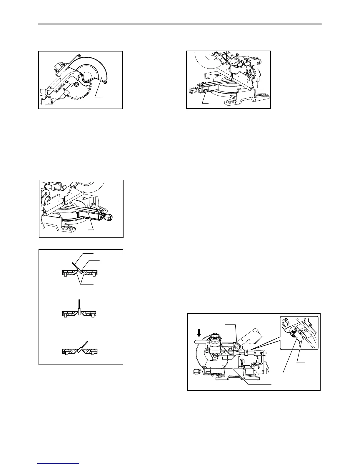
Maintaining maximum cutting capacity
This tool is factory adjusted to provide the maximum
cutting capacity for a 260 mm saw blade.
Unplug the tool before any adjustment is attempted.
When installing a new blade, always check the lower limit
position of the blade and if necessary, adjust it as follows:
1
2
3
4
009518
1. Adjusting bolt
2. Turn base
3. Stopper lever
4. Slide pipe
1. Lock lever
2. Locking screw
1. Saw blade
2. Blade teeth
3. Kerf board
4. Left bevel cut
5. Straight cut
6. Right bevel cut
1. Kerf board
1. Blade guard
 Loading...