Do you have a question about the Makita RP1803F and is the answer not in the manual?
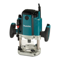
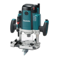
This document provides an instruction manual for Makita Router models RP1802, RP1802F, RP1803, RP1803F, RP2302FC, and RP2303FC. It includes safety warnings, functional descriptions, operating instructions, and maintenance guidelines.
The router is intended for flush trimming and profiling of wood, plastic, and similar materials. It features a double insulation design for enhanced safety and includes a "Read before use" instruction, emphasizing the importance of understanding the manual.
The router is equipped with several features to facilitate precise and safe operation:
Depth Adjustment: The depth of cut can be adjusted using a lock lever, an adjusting hex bolt, a stopper block, an adjusting knob, a depth pointer, a stopper pole, a stopper pole setting nut, and a fast-feed button. To set the depth, the tool is placed on a flat surface, the lock lever is loosened, and the tool body is lowered until the router bit touches the surface. The stopper pole setting nut is turned counterclockwise, and the stopper pole is lowered to contact the adjusting hex bolt. The depth pointer is aligned with the "0" graduation. The desired depth is achieved by pressing the fast-feed button and raising the stopper pole. Minute adjustments can be made by turning the adjusting knob (1 mm per turn). The stopper pole can then be fastened by turning the stopper pole setting nut clockwise. The predetermined depth of cut is obtained by loosening the lock lever and lowering the tool body until the stopper pole contacts the adjusting hex bolt.
Nylon Nut: The nylon nut allows for adjustment of the upper limit of the tool body. Users are cautioned not to lower the nylon nut too low, as this could cause the router bit to protrude dangerously.
Stopper Block: The stopper block features three adjusting hex bolts, which raise or lower by 0.8 mm per turn. This allows for easily obtaining three different depths of cut without readjusting the stopper pole, making it convenient for progressively deeper bit settings when cutting deep grooves. However, users are cautioned against excessive cutting depths to avoid motor overload or difficulty controlling the tool. For an 8 mm diameter bit, the depth of cut should not exceed 15 mm per pass, and for a 20 mm diameter bit, it should not exceed 5 mm per pass. For extra-deep grooving, two or three passes with progressively deeper bit settings are recommended.
Switch Action: The tool is equipped with a lock button to prevent accidental pulling of the switch trigger. To start the tool, the lock button is depressed, and the switch trigger is pulled. Releasing the switch trigger stops the tool. For continuous operation, the lock button is depressed further while the switch trigger is pulled. To stop continuous operation, the switch trigger is pulled, allowing the lock button to return automatically, then the switch trigger is released. After releasing the switch trigger, a lock-off function prevents the switch trigger from being pulled. Users are advised to hold the tool firmly when turning it off to manage the reaction force.
Electronic Functions: The tool incorporates electronic functions for ease of operation.
Lighting up the Lamps (RP1802F, RP1803F, RP2302FC, RP2303FC only): Pulling the switch trigger turns on the lamp, which remains lit while the trigger is pulled and turns off approximately 10 seconds after release. Users are cautioned not to look directly at the light source.
Installing/Removing Router Bit: Router bits are inserted all the way into the collet cone. The shaft lock is pressed to keep the shaft stationary, and a wrench is used to securely tighten the collet nut. For smaller shank bits, a collet sleeve is inserted first. To remove the bit, the process is reversed. Users are cautioned to install the bit securely, use only the provided wrench, and not to tighten the collet nut without a bit or install small shank bits without a collet sleeve, as this can damage the collet cone.
Operation: Before operation, ensure the stopper pole is firmly secured by its setting nut to prevent depth changes and personal injury. Verify that the tool body automatically rises to the upper limit and the router bit does not protrude from the tool base when the lock lever is loosened. Always use both grips and hold the tool firmly. Ensure the chip deflector is properly installed.
Straight Guide: Used for straight cuts, chamfering, or grooving. It is installed on the guide holder using a clamping screw (B), and the guide holder is inserted into the holes in the tool base and secured with clamping screw (A). The distance between the router bit and the straight guide can be adjusted by loosening clamping screw (B) and turning the fine adjusting screw. For wider workpieces or non-straight sides, a straight board can be clamped to the workpiece and used as a guide. Extra pieces of wood can be bolted to the guide for wider dimensions or to prevent large diameter bits from striking the guide.
Fine Adjusting Straight Guide (Optional Accessory): Two rods are inserted into the outer mounting slots of the guide holder and secured with clamping screws (B). A thumb screw (A) is tightened, and the rods are inserted into the base and secured with clamping screws (A).
Templet Guide (Optional Accessory): This guide provides a sleeve for the router bit, allowing use with templet patterns. To install, pull the lock plate lever and insert the templet guide. The templet is secured to the workpiece, and the tool is moved with the templet guide sliding along its side. Note that the workpiece will be cut slightly differently in size from the templet, and the distance (X) can be calculated using the provided equation: (outside diameter of the templet guide - router bit diameter) / 2.
Trimmer Guide (Optional Accessory): Used for trimming and curved cuts in veneers. It is installed on the guide holder using clamping screw (D), and the guide holder is inserted into the holes in the tool base and secured with clamping screw (A). The distance between the router bit and the trimmer guide can be adjusted by loosening clamping screw (D) and turning the fine adjusting screw. The guide roller's height can be adjusted by loosening clamping screw (C). When cutting, the tool is moved with the guide roller riding the side of the workpiece.
Dust Nozzle Sets: Used for dust extraction. The dust nozzle is installed on the tool base using a thumb screw, ensuring its protrusion fits into the notch in the tool base. A vacuum cleaner can then be connected to the dust nozzle.
Screw M6 x 135 for Depth Adjustment: When using the tool with a router table, this screw allows for small depth adjustments from above the table (1.0 mm per full turn). Turning it clockwise increases depth, and counterclockwise decreases it. To install, a flat washer is attached to the screw, which is then inserted through a screw hole on the tool base and screwed into the threaded part of the motor bracket. Grease or lubricating oil should be applied to the screw hole and threaded part.
General Maintenance: Always ensure the tool is switched off and unplugged before any inspection or maintenance. Never use gasoline, benzine, thinner, alcohol, or similar substances, as they can cause discoloration, deformation, or cracks. For product safety and reliability, repairs and adjustments should be performed by Makita Authorized or Factory Service Centers using genuine Makita replacement parts.
Replacing Carbon Brushes: Carbon brushes should be checked regularly and replaced when they wear down to the limit mark. Keep them clean and free to slip in their holders. Both brushes should be replaced simultaneously with identical carbon brushes. To replace, use a screwdriver to remove the brush holder caps, take out the worn brushes, insert new ones, and secure the caps.
The manual emphasizes several safety warnings, including:
| Brand | Makita |
|---|---|
| Model | RP1803F |
| Category | Wood Router |
| Language | English |