Wiring diagram
P 9/ 9
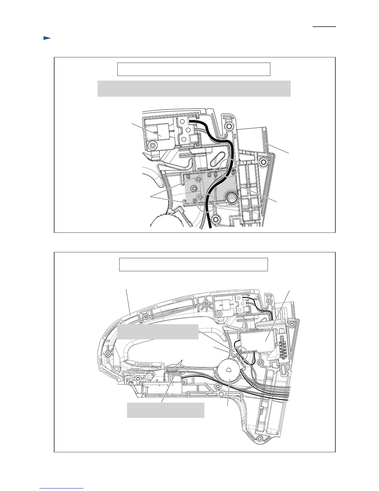
Handle Section before assembling Handle Switch
Before assembling Handle switch, fix Lead wires (blue, orange) to Main switch
with Lead wire holders as drawn below.
Fig. D-5
Fig. D-6
Lead wires (blue, orange)
Main switch
Place for
Handle switch
Handle Section after assembling Handle Switch
Handle switch
Handle set (L)
Handle set (L)
Lead wire holder
Pass Lead wire from Controller
between Ribs.
Terminal
Fix Lead wires of Handle switch
with Lead wire holder
Ribs
Dial

 Loading...