Repair
[2] LUBRICATION
Apply Makita grease N. No.2 to the following portion to protect parts and product from unusual abrasion. Refer to Fig. 5.
1) Gear room (6g: Refer to Fig. 5.)
2) Contact portion of Shear blade ass’y and Crank (3g: Refer to Fig. 7)
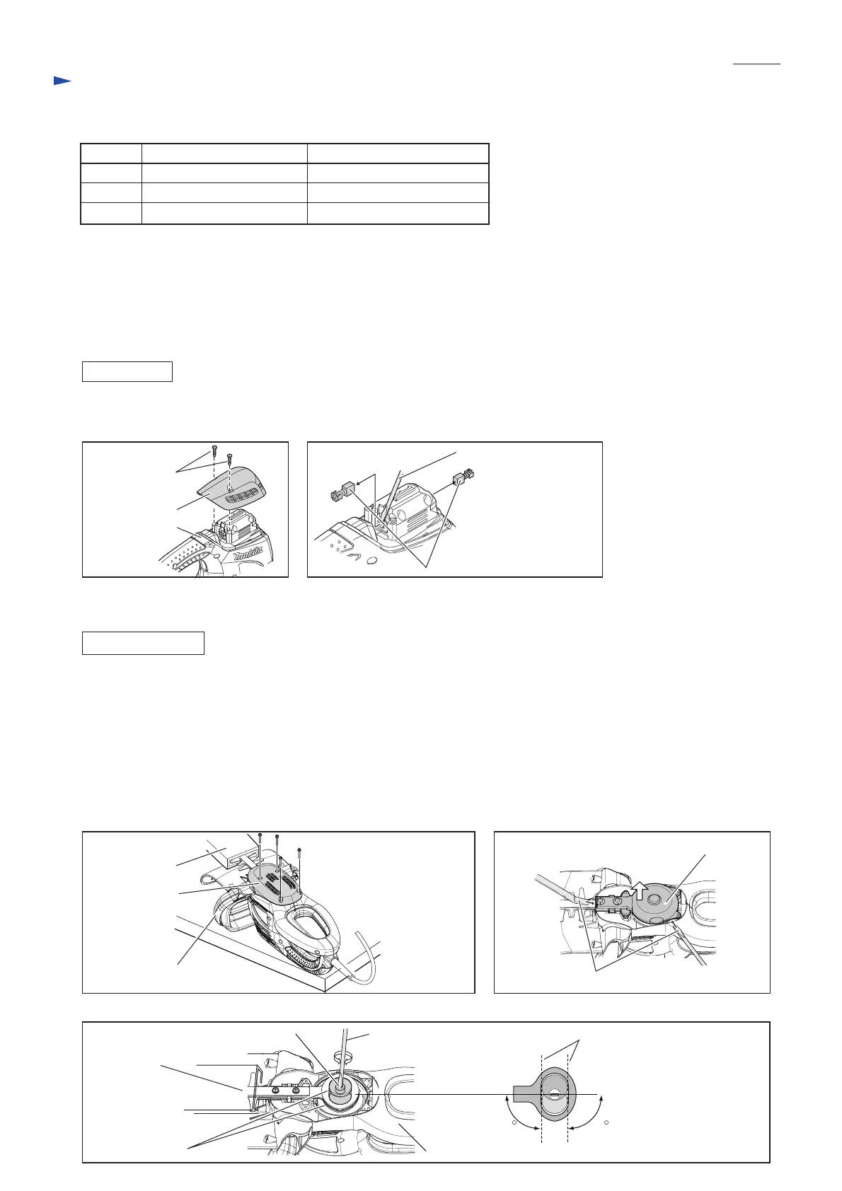
Remove two 4x18 Tapping screws and Top cover from Housing set. (Fig. 1)
Pick out two Carbon brushes using thin slotted screwdriver. (Fig. 2)
[3] DISASSEMBLY/ASSEMBLY
[3] -1. Carbon brush
[3] DISASSEMBLY/ASSEMBLY
[3] -2. Shear blade ass’y and Gear ass’y
[1] NECESSARY REPAIRING TOOLS
CAUTION: Unplug the machine for safety before repair/ maintenance !
1) Turn the machine upside down and keep it in a horizontal position by the use of a horizontal portion of Front grip.
2) Remove four M4x25 Pan head screws and Under cover. (Fig. 3)
Note: Set Blade cover in place to prevent being injured as illustrated in Fig. 3.
3) Remove Gear housing cover by levering with two 1R263 or slotted screwdrivers. (Fig. 4)
4) Turn crank portion with slotted screwdriver inserted to the groove on Spindle. (Fig.5) Two oval holes of Shear blades
and the crank portion of Gear ass’y have to be aligned as illustrated in Fig. 5.
Note: It is possible that Two oval holes of Shear blades and the crank portion of Gear ass’y do not be aligned because
Gear ass’y is in locked position by Pin 5. Turn Spindle counterclockwise with strong force to release the locked
condition. (The spring and the lock washer in Gear ass’y will be slid, and Pin 5 will be out of the locked position.)
DISASSEMBLING
Fig. 3
Slotted
screwdriver
groove on Spindle of Gear ass’y Tangential lines of Crank portion and straight lines
of Shear blades’ oval holes
Viewed from the upper sideHousing set
Center line of Housing set
and Shear blade ass’y
90
Fig. 5
Fig. 1 Fig. 2
Fig. 4
Code No. Description
1R003 Retaining ring pliers ST-2N Removing Lifter section
1R212 Tip for Retaining ring pliers Modular use with 1R003
1R263 Bearing extractor Removing Gear housing cover
Use for
P 2/ 7
REPLACING
Blade cover
Under cover
Gear housing cover
Front grip
1R263 or Slotted screwdriver (2pcs.)
M4x25 Pan head
screw (4pcs.)
Oval holes of
Shear blades
(one hole each)
Blade cover
90
4x18 Tapping
screw (2pcs.)
Thin slotted screwdriver
Top cover
Housing set
Carbon brush (2pcs.)
 Loading...