9
ITALIANOENGLISHFRANÇAISDEUTSCH
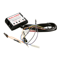
CDI
• Carburation adjusting
• at min/medium/max
• RPM limiter: RPM
• dierent maps
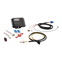
CDI assembly Fig.
• Position the Force Master
CDI into the helmet holder
Fig. and run the wires to the
engine, taking care that they
will not be damaged.
• Follow the wire that exits
the injector and determine
its connector, disconnect
this original connector and
reconnect with the two
connectors from the Malossi
ECU Fig. , part. A.
• Connect the black wire which
comes from the Malossi CDI to
the throttle Fig. , part. B.
• Locate the original coil and
disconnect the connector.
• Insert the connector which
comes from the Malossi ECU to
the original coil.
• Connect the original
connector to the ECU’s
bypass to complete the circuit
Fig. , part. C.
• Locate the diagnosis connector
of the vehicle Fig. ,
positioned as indicated in
Fig. ABC
• Remove the protection tap
from the original connector
and put in the Malossi
connector Fig.
• Fix the CDI.
TPS Throttle Position
Sensor Calibration – Fig.
• Rotate the “LOW” trimmer to
the red arrow position.
• Turn the ignition key to the
“ON” position.
• Wait for all three LEDs to
illuminate and then turn o.
• Turn the ignition key to the
“OFF” position.
• Rotate the “LOW” trimmer to
the “ZERO ” position.
• Rotate the “HIGH” trimmer to
the red arrow position.
• Turn the throttle to the fully
open position.
• Turn the ignition key to the
“ON” position.
• Wait for all three LEDs to
illuminate and then turn o.
• Turn the ignition key to the
“OFF” position.
• Rotate the “HIGH” trimmer to
the “ZERO ” position.
If the red LED starts blinking while
calibrating the MIN and MAX,
 Loading...