Model PR-274/27
Technical Informatio
TI.274/275-0
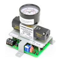
Low Pressure Transducer
+ –
Z S
High Low
+ –
Z S
High Low
Legend
S = Span Adjust
Z = Zero Adjust
+ = Supply Voltage
- = Output
Caution: If you are using grounded AC, the hot wire must be on
the (+) terminal. Also, if you are using a controller without built-in
isolation, use an isolation transformer to supply the PR-274/275
transducer.
PR-274
(mA output)
PR-275
(mA output)
Wiring PR-274/275 Units with VDC Output
PR-274/275 pressure transducers with Vdc output are field selectable
0-5 VDC or 0-10 VDC output and can be powered with either 12-40
VDC or 12-35 VAC. The following describes the proper wiring of these
pressure transducers with VDC output:
1. Remove the blue terminal block by carefully pulling it off the circuit
board.
2. Locate the (+), (-), and (0) terminal markings on the board.
3. Attach the power wires to the (+) and (-) terminals. The (-) terminal
is also the negative output terminal.
4. Connect the (0) terminal, which is the positive VDC output terminal,
to the controller’s input.
5. Re-insert the terminal block to the circuit board and apply power to
the unit.
6. Check the appropriate VDC output using a voltmeter set on DC volts
across the (0) and (-) terminals.
TYPICAL APPLICATIONS (wiring diagrams)
Caution: This product contains a half-wave rectifier power supply
and must not be powered off transformers used to power other
devices utilizing non-isolated full-wave rectifier power supplies.
Caution: When multiple PR-274/275 units are powered from the
same transformer, damage will result unless all 24G power leads
are connected to the same power lead on all devices. It is mandatory
that correct phasing be maintained when powering more than one
device from a single transformer.
PR-274/275 Pressure Transducers with mA Output
Page 2 of 5
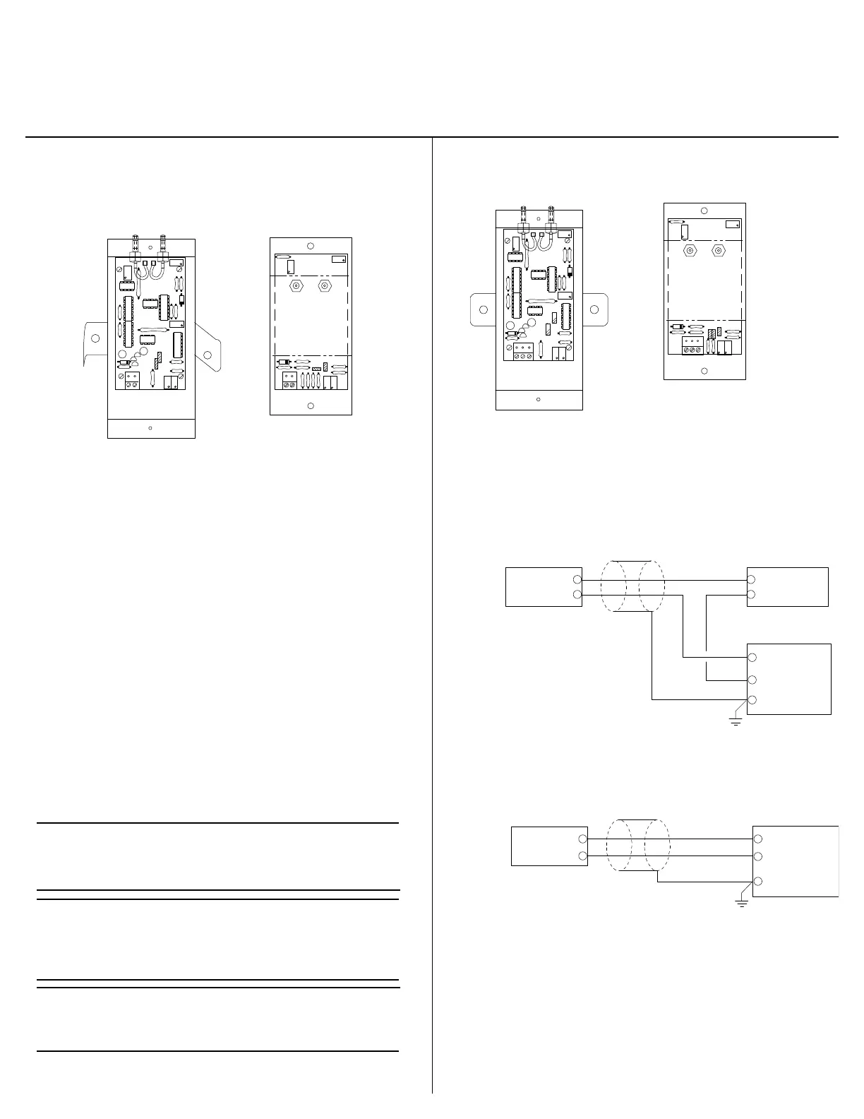
Figure-1 and Figure-2
Illustrate typical wiring diagrams for the PR-274/275, 4-20 mA,
two-wire low pressure transducers.
+
–
+
–
+
–
mA Output
Transducer Only
12-40 VDC
Powr Supply
Controller/
Meter/
Recorder
Shield/
Ground
Input Signal
Common
Figure-1 Wiring for mA Low Pressure
Transducers with External DC
Power Supply
+
–
mA Output
Tranducer Only
+
–
Controller/
Meter/
Recorder
Shield/
Ground
Input Signal
Common
Figure-2 Wiring for mA Low Pressure Transducers
Where Controller or Meter has Internal DC
Power Supply
+ - 0
Legend
S = Span Adjust + = Supply Voltage (Hot)
Z = Zero Adjust - = Common (Neutral)
0 = Input
PR-274/275 Pressure Transducers with VDC Output
PR-274
(VDC output)
PR-275
(VDC output)
High Low
+ - 0
Z S
High
Low
 Loading...