CALIBRATION All units are factory calibrated to meet or exceed
published specifications. If field adjustment is necessar
follow the instructions below.
Calibration of PR-274/275 mA Units
1.Connect terminals (+) and (-) to the appropriate
power source.
2.Connect the DVM in series on the (-) terminal.
3.Apply low pressure to the unit and carefully adjus
the zero trimmer (Z) to obtain desired low output.
4.Apply high pressure to the unit and adjust span
trimmer (S) to obtain the desired high output
pressure.
5.Repeat steps 3 and 4 until desired calibration is
achieved.
Range: A Range: B
Range: C Range: D
Range: E
Range: F
Range: G
Range: H
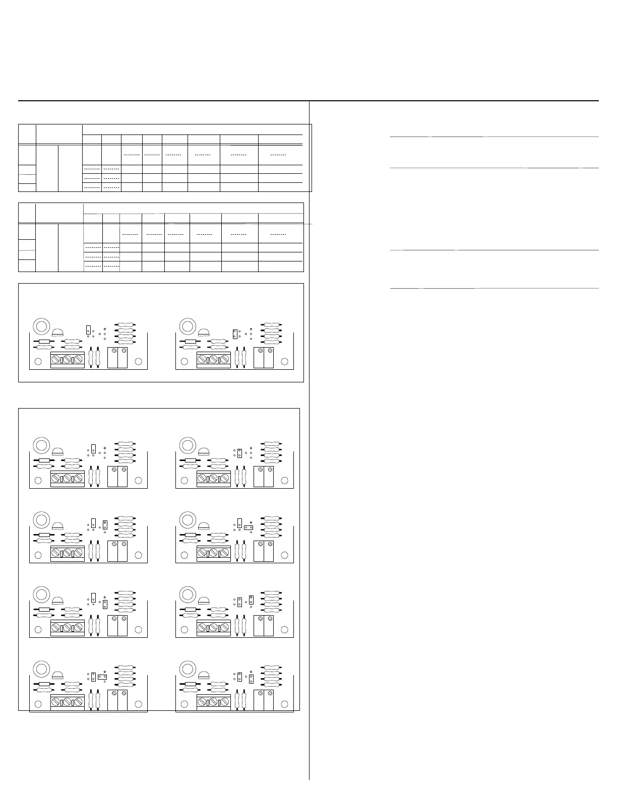
Figure-6 Jumper Selections for Low Pressure Transducers
with VDC Outputs.
+ – 0
Z S
+ – 0
Z S
+ – 0
Z S
+ – 0
Z S
+ – 0
Z S
+ – 0
Z S
+ – 0
Z S
+ – 0
Z S
RANGE CONFIGURATIONS
MAINTENANCE Regular maintenance of the total system is
recommended to assure sustained optimum
performance.
FIELD REPAIR None. Replace with a functional unit.
WARRANTY See Data Sheet for additional information.
Model PR-274/27
Technical Information
TI.274/275-0
Low Pressure Transducer
Page 4 of 5
Calibration of PR-274/275 VDC Units
1.Connect terminals (+) and (-) to the appropriate
power source. The (-) terminal is also the negative
output terminal.
2.Connect the DVM on DC volts across (0) and (-)
terminal.
3.Apply low pressure to the unit and carefully adjust
the zero trimmer (Z) to obtain desired low output.
4.Apply high pressure to the unit and adjust span
trimmer (S) to obtain the desired high output
pressure.
5.Repeat steps 3 and 4 until desired calibration is
achieved.
CHECKOUT 1. Verify that the unit is mounted in the correct position
2.Verify appropriate input signal and supply voltage
Caution: Never connect 120 VAC to these
transducers. Never connect AC voltage to a unit
intended for DC supply.
3.Verify appropriate configuration range.
Transducer This is a rough functional check only.
Operation 1.Adjust the pressure to obtain maximum output signa
for appropriate range.
2.Output should be 20 mA or 5 or 10 VDC.
3.Adjust the pressure to obtain minimum output signa
4.Output should be 4 mA or 0 VDC.
Note: The PR-274/275 is a highly accurate device.
For applications requiring a high degree of accuracy
the use of laboratory quality meters and gauges are
recommended.
0 TO 5 VDC
+ – 0
Z S
0 to 10 VDC
+ – 0
Z S
OUTPUT
CONFIGURATIONS
Table-2 Range Configurations for Low Pressure Transducers
with VDC Outputs.
A
Range
B C D E
F
G H
Range Configurations (inches w.c.)
R2
R3
R4
0 to .10
-0.05 to
+0.05
0 to 1.0
0 to 5.0
0 to 30
0 to 0.5
0 to 2.5
0 to 15
0 to 0.25
0 to 1.25
0 to 7.5
-0.5 to +0.5
-2.5 to +2.5
-15.0 to +15.0
-0.25 to +0.25
-1.25 to +1.25
-7.5 to +7.5
-0.125 to +0.125
-0.625 to +0.625
-3.75 to +3.75
A B C
D E
F
G H
Range Configurations (pa)
0 to 25
-12.5 to
+12.5
0 to 250
0 to 1250
0 to 7500
0 to 125
0 to 625
0 to 3750
0 to 62.5
0 to 312.5
0 to 1875
-125 to +125
-625 to +625
-3750 to +3750
-62.5 to +62.5
-312.5 to +312.5
-1875 to +1875
-31.25 to +31.25
-156.25 to +156.25
-937.5 to +937.5
R1
Output
Configurations
0 to
5 VDC
0 to
10 VDC
ange
R6
R7
R8
R5
Output
Configurations
0 to
5 VDC
0 to
10 VDC
 Loading...