EasyManua.ls Logo

Mamiya RB67Pro-S - User Manual

Mamiya RB67Pro-S
6 pages
Print Icon
To Next Page IconTo Next Page
Loading...
Auto Extension Tubes
English
Question and Answer IconNeed help?

Do you have a question about the Mamiya RB67Pro-S and is the answer not in the manual?

Summary

Attaching Auto Extension Tubes

Connecting Method of No. 1 and No. 2 Tubes

Explains the procedure for connecting both auto extension tubes.

Removing Auto Extension Tubes

Photographing with Extension Tubes

How to Find the Exposure Compensation Value

Details calculating exposure compensation using bellows extension and scale.

Overview

This manual describes the Mamiya RB67 Pro-S/RB67 Auto Extension Tubes, which are designed to facilitate close-up photography at distances closer than the shortest focusing range of the lens. These extension tubes are an integral accessory for photographers seeking to expand the macro capabilities of their Mamiya RB67 camera system.

Function Description

The primary function of the auto extension tubes is to increase the distance between the lens and the film plane, effectively allowing the lens to focus on subjects at much closer ranges than it would ordinarily permit. This increased lens-to-film distance results in a larger image magnification, which is crucial for close-up and macro photography.

A key feature of these extension tubes is their "auto" designation, which signifies that they maintain the interlock between the lens shutter and aperture. This means that when using the extension tubes, the camera system operates much like it would during ordinary photography, simplifying the process of close-up shooting or copying. The automatic diaphragm coupling ensures that the lens aperture can be controlled from the camera body, and the shutter remains synchronized, providing a seamless shooting experience despite the added extension.

The manual details two types of auto extension tubes: No. 1 and No. 2. These tubes have different lengths, with No. 1 measuring 45 mm and No. 2 measuring 82 mm. The availability of two distinct lengths offers flexibility, allowing photographers to choose the appropriate extension for their desired magnification and working distance. Furthermore, the tubes are designed to be used in combination, meaning both No. 1 and No. 2 can be stacked together to achieve even greater magnification. This modularity provides a wide range of close-up possibilities, from moderate magnification with a single tube to higher magnifications with both tubes combined.

Usage Features

The manual provides clear, step-by-step instructions for attaching and removing the auto extension tubes, as well as for connecting them to each other and to the camera body.

Prior to Attaching the Auto Extension Tube:

Before attaching an extension tube, it is essential to prepare the camera and the tube itself.

  1. Cock the Mirror: The first step involves fully pushing down the shutter cocking lever on the camera to cock the mirror. This ensures the camera is in a ready state for lens attachment.
  2. Cock the Extension Tube: The cocking pins on the auto extension tube must be turned to the red cocking position marks. These pins are spring-loaded and will return to the green marks when released, indicating that the tube is cocked. This step is crucial for maintaining the automatic diaphragm coupling.
  3. Cock the Lens Shutter: In addition to cocking the extension tube, the lens shutter must also be cocked. This ensures proper synchronization between the lens, extension tube, and camera body.

Attaching the Auto Extension Tube:

The attachment process involves a specific sequence to ensure proper alignment and secure connection.

  1. Align Bayonet Rings: To attach the extension tube to the camera body, the red dot on the bayonet ring of the extension tube must be aligned with the red dot on the camera body. Similarly, when attaching the lens to the extension tube, the red dot on the lens bayonet ring should be aligned with the red line on the extension tube.
  2. Mount and Secure: Once aligned, the extension tube is mounted onto the camera body, and the bayonet ring is firmly turned clockwise to secure it. The same procedure applies when attaching the lens to the extension tube. If the lens does not fit smoothly, the manual advises gently turning the lens left and right while pushing it against the extension tube.

Connecting No. 1 and No. 2 Tubes:

When combining both extension tubes for higher magnification, the process is similar:

  1. Cock Both Tubes: Both auto extension tubes must be cocked by turning their respective cocking pins.
  2. Align and Connect: The red dot on the bayonet ring of one tube is aligned with the red dot on the other tube, and they are connected. The manual notes that either tube can be placed in front when combining them.
  3. Mount to Camera and Attach Lens: After connecting the tubes, the combined unit is mounted onto the camera body, and then the lens is attached to the front of the combined extension tubes.

Removing the Auto Extension Tube:

Removal of the extension tubes and lens also follows a specific order:

  1. Cock Shutter Cocking Lever: Fully press down the shutter cocking lever.
  2. Remove Lens: Turn the bayonet ring of the lens counterclockwise and remove the lens.
  3. Remove Extension Tube: Turn the bayonet ring of the extension tube counterclockwise and remove it from the camera body.

A helpful note in the manual clarifies that the auto extension tube can be detached from the camera body with the lens still attached. However, if the lens is subsequently detached from the extension tube, it is important to always confirm that the lens shutter is cocked.

Photographing with Extension Tubes:

The manual emphasizes that because the auto extension tube interlocks with the lens's automatic diaphragm, the general photographing method remains the same as for common procedures. However, a critical difference lies in the exposure compensation required due to the increased lens-to-film distance. The manual provides a "Close-up Table" to guide photographers in correcting exposure.

Exposure Compensation:

After focusing the lens, the extension amount is read from the bellows extension scale. This value is then used in conjunction with the close-up photography table to determine the necessary exposure compensation. For example, if a 127mm lens combined with a No. 2 auto extension tube shows an extension of 31mm on the bellows scale, the table might indicate a +2 steps compensation. This means the photographer should use a two-step slower shutter speed or a two-step larger aperture (smaller f-number) to increase the exposure accordingly. The table provides compensation values in 1/2 stop increments, but for precise exposure, intermediate values (e.g., +1 1/4 or +1 3/4) should be considered.

Specific Recommendations for Photography:

  • Mirror-up Photography: For close-up photography with the auto extension tube, mirror-up photography (independent mirror release) is recommended. This minimizes camera shake, which can be particularly critical at high magnifications.
  • Small Aperture: When photographing through extension tubes, using as small an aperture as possible is advised. This helps to maximize depth of field, which becomes very shallow in macro photography.
  • Tube Combinations: The manual advises against using combinations other than No. 1 + No. 2 (e.g., No. 2 + No. 2). This suggests that certain combinations might not yield optimal results or could lead to mechanical issues.
  • Vignetting: When photographing in the 6 × 7 format, if the 127mm lens is used, minimal or no corner vignetting will occur with one extension tube. However, using lenses other than the 127mm with two extension tubes (No. 1 and No. 2) may result in some vignetting in the four corners of the picture. With Polaroid Land film packs, corner vignetting increases due to the larger picture size, but a central 6 x 7cm portion will remain clear.
  • Lens Compatibility: For the 65mm lens, only one auto extension tube No. 1 should be used. The 50mm lens should not be used with extension tubes, as it decreases resolving power due to exceeding life-size magnification.

Maintenance Features

While the manual does not explicitly detail "maintenance features" in the traditional sense (e.g., cleaning instructions or repair guidelines), the design and operational instructions inherently contribute to the longevity and proper functioning of the device.

  • Proper Attachment/Removal Procedures: The detailed steps for attaching and removing the tubes and lenses are crucial for preventing damage to the bayonet mounts on the camera, lenses, and extension tubes themselves. Forcing components or misaligning them can lead to wear and tear or breakage.
  • Confirmation of Cocking Pins: The instruction to confirm that the lens shutter is cocked after detaching the lens from the extension tube (even if the tube was removed from the camera with the lens attached) is a preventative measure. It ensures that the mechanical linkages are in the correct state for subsequent use, preventing potential issues with shutter operation.
  • Avoiding Incompatible Combinations: The warning against using certain tube combinations (e.g., No. 2 + No. 2) and specific lenses (e.g., 50mm lens with any extension tube) serves as a maintenance guideline. Adhering to these recommendations prevents mechanical stress, optical degradation, or other issues that could arise from unsupported configurations.
  • Smooth Operation: The advice to gently turn the lens left and right while pushing it against the extension tube if it doesn't fit smoothly indicates a design consideration for user interaction that also helps prevent damage from forceful attachment.

In essence, the "maintenance" aspect of this manual is embedded within the correct operational procedures, guiding the user to handle the equipment in a way that preserves its functionality and extends its lifespan. The emphasis on precise alignment and gentle handling, combined with warnings about incompatible setups, ensures that the auto extension tubes and the associated camera system remain in optimal working condition.
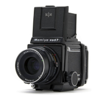
Mamiya RB67Pro-S Specifications

General IconGeneral
TypeMedium format SLR camera
Film Format120/220 roll film
Focusing ScreenInterchangeable
Mirror Lock-UpYes
Image Size6x7 cm
Lens MountMamiya bayonet mount
Shutter Speed1/400 sec to 1 sec, Bulb
MeteringNone (external meter required)
FocusingManual focusing
ViewfinderInterchangeable waist-level or prism finders
Exposure MeterNone (external meter required)
Film AdvanceManual

Related product manuals