Diagram
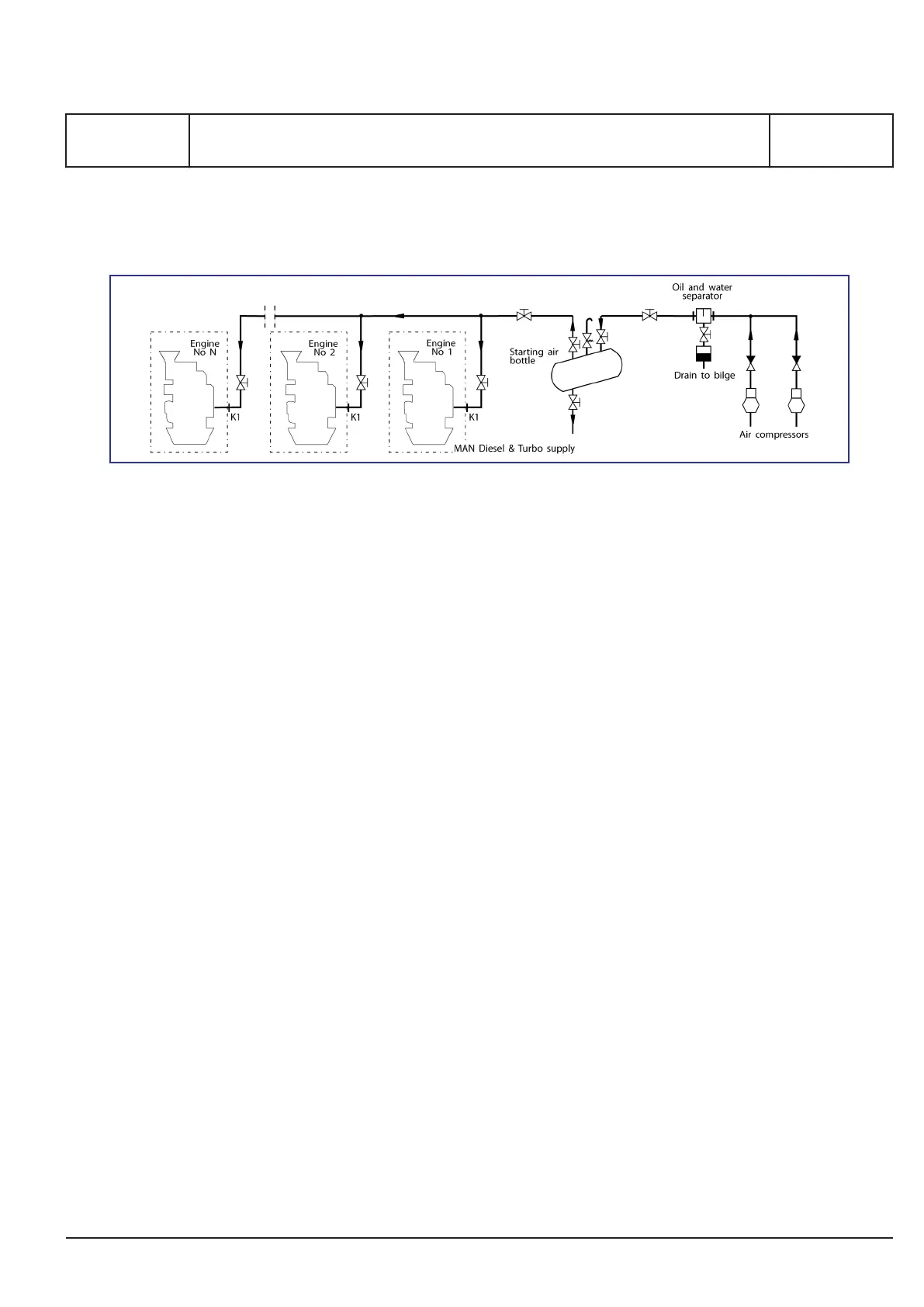
Figure 1: Diagram for compressed air system
Design of external system
The external compressed air system should be
common for both propulsion engines and GenSet
engines.
Separate tanks shall only be installed in turbine ves-
sels, or if GenSets in engined vessels are installed
far away from the propulsion plant.
The design of the air system for the plant in ques-
tion should be according to the rules of the relevant
classification society.
As regards the engine's internal compressed air
system, please
see B 14 00 0 "Internal Com-
pressed Air System".
An oil and water separator should be mounted
between the compressor and the air receivers, and
the separator should be equipped with automatic
drain facilities.
Each engine needs only one connection for com-
pressed air, please
see diagram for the compressed
air system.
Installation
In order to protect the engine's starting and control
equipment against condensation water, the follow-
ing should be observed:
▪ The air receiver(s) should always be installed
with good drainage facilities. Receiver(s)
arranged in horizontal position must be installed
with a slope downwards of min. 3°-5°.
▪ Pipes and components should always be trea-
ted with rust inhibitors.
▪ The starting air pipes should be mounted with a
slope towards the receivers, preventing possi-
ble condensed water from running into the
compressors.
▪ Drain valves should be mounted at the lowest
position on the starting air pipes.
MAN Diesel & Turbo
1655207-3.2
Page 1 (1)
Compressed air system
B 14 00 0
L27/38S, L21/31S, L16/24S, L16/24, L21/31, L27/38
2015.11.27 - NG
 Loading...