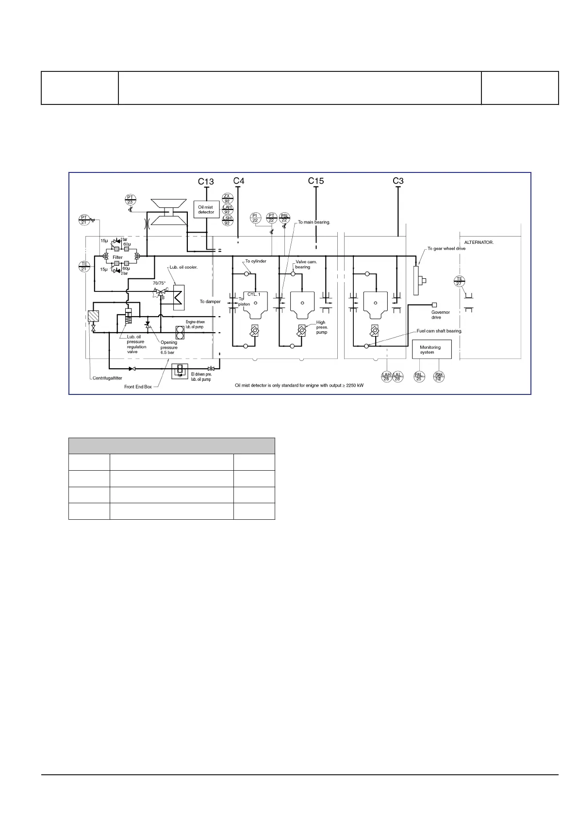
Internal lubricating oil system
Figure 1: Diagram for internal lubricating oil system
Pipe description
C3 Lubricating oil from separator DN25
C4 Lubricating oil to separator DN25
C13 Oil vapour discharge* DN100
C15 Lubricating oil overflow DN50
Table 1: Flange connections are as standard according to DIN
2501
* For external pipe connection,
please see Crank-
case ventilation, B 12 00 0/515.31
.
General
As standard the lubricating oil system is based on
wet sump lubrication.
All moving parts of the engine are lubricated with oil
circulating under pressure in a closed system.
The lubricating oil is also used for the purpose of
cooling the pistons and turbocharger.
The standard engine is equipped with:
▪ Engine driven lubricating oil pump
▪ Lubricating oil cooler
▪ Lubricating oil thermostatic valve
▪ Duplex full-flow depth filter
▪ Pre-lubricating oil pump
▪ Centrifugal by-pass filter
Oil quantities
The approximate quantities of oil necessary for a
new engine, before starting up are given in the
table, see "
B 12 01 1 / 504.06 / 604.06 Lubricating
Oil in Base Frame
" (max. litre H3)
If there are connected external, full-flow filters etc.,
the quantity of oil in the external piping must also be
taken into account.
Max. velocity recommendations for external lubri-
cating oil pipes:
- Pump suction side 1.0 - 1.5 m/s
- Pump discharge side 1.5 - 2.0 m/s
Lubricating oil consumption
The lubricating oil consumption, see "
Specific lubri-
cating oil consumption - SLOC, B 12 15 0 /
504.07
"
MAN Diesel & Turbo
1693562-4.4
Page 1 (3)
Internal lubricating oil system
B 12 00 0
L27/38S, L27/38
2014.08.22 - Dr. Horn
 Loading...