3-38
H - OCCASIONAL MAINTENANCE
H1 - FUEL SYSTEM
BLEED
These operations are to be carried out only in the following cases:
• A component of the fuel system replaced.
• A drained tank.
• Running out of fuel.
Ensure that the level of fuel in the tank is sufficient and bleed in the following order:
- Open the I.C. engine bonnet.
- Put the ignition on for three minutes on the lift truck, to give the lift pump time to release
air from the filter.
- Switch off the ignition with the ignition key.
BLEEDING THE INJECTORS
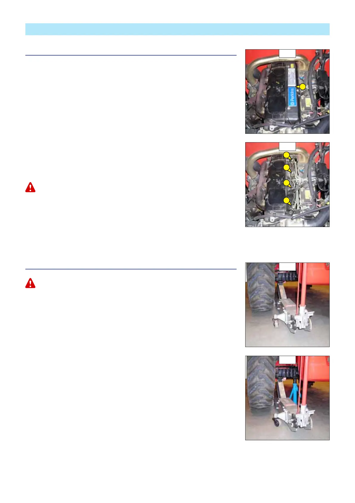
- Remove the injectors cover 1 (fig. H1/1).
- Loosen high pressure connectors 2 (fig. H1/2) of all the injectors.
- Activate the starter until the diesel fuel flows out free of air at high pressure connectors 2
(fig. H1/2).
Do not engage the starter motor on a continual basis for more than 30 seconds and let it cool between
unsuccessful attempts.
- Tighten the connections while the diesel fuel is flowing out (tightening torque 30 N.m).
- So the I.C. engine is ready to be started up.
- Turn the I.C. engine over slowly for 5 minutes immediately after bleeding the fuel feed
circuit, in order to ensure that the injection pump has been bled thoroughly.
NOTE: If the I.C. engine functions correctly for a short time then stops or functions
irregularly, check for possible leaks in the low pressure circuit. If in doubt, contact your dealer.
H2 - WHEEL
CHANGE
In the event of a wheel being changed on the public highway, make sure of the following points:
For this operation, we advise you to use the hydraulic jack MANITOU reference 505507 and
the safety support MANITOU reference 554772.
- Stop the lift truck, if possible on even and hard ground.
- To pass on stop of lift truck (see: 1 - OPERATING AND SAFETY INSTRUCTIONS: DRIVING
INSTRUCTIONS UNLADEN AND LADEN).
- Put the warning lights on.
- Immobilise the lift truck in both directions on the axle opposite to the wheel to be changed.
- Unlock the nuts of the wheel to be changed.
- Place the jack under the flared axle tube, as near as possible to the wheel and adjust the
jack (fig. H2/1).
- Lift the wheel until it comes off the ground and put in place the safety support under the
axle (fig. H2/2).
- Completely unscrew the wheel nuts and remove them.
- Free the wheel by reciprocating movements and roll it to the side.
- Slip the new wheel on the wheel hub.
- Refit the nuts by hand, if necessary grease them.
- Remove the safety support and lower the lift truck with the jack.
- Tighten the wheel nuts with a torque wrench (see: 3 - MAINTENANCE: A - DAILY OR EVERY
10 HOURS SERVICE for tightening torque).
H2/1
H2/2
H1/1
1
H1/2
2
2
2
2