EasyManuals Logo

Manitowoc National Crane NBT40 Series User Manual

Manitowoc National Crane NBT40 Series
128 pages
To Next Page IconTo Next Page
To Previous Page IconTo Previous Page
Page #25 background imageLoading...
Page #25 background image
National Crane Published 4-23-2018 Control # 239-11 2-11
NBT40 SERIES OPERATOR MANUAL SAFETY INFORMATION
2
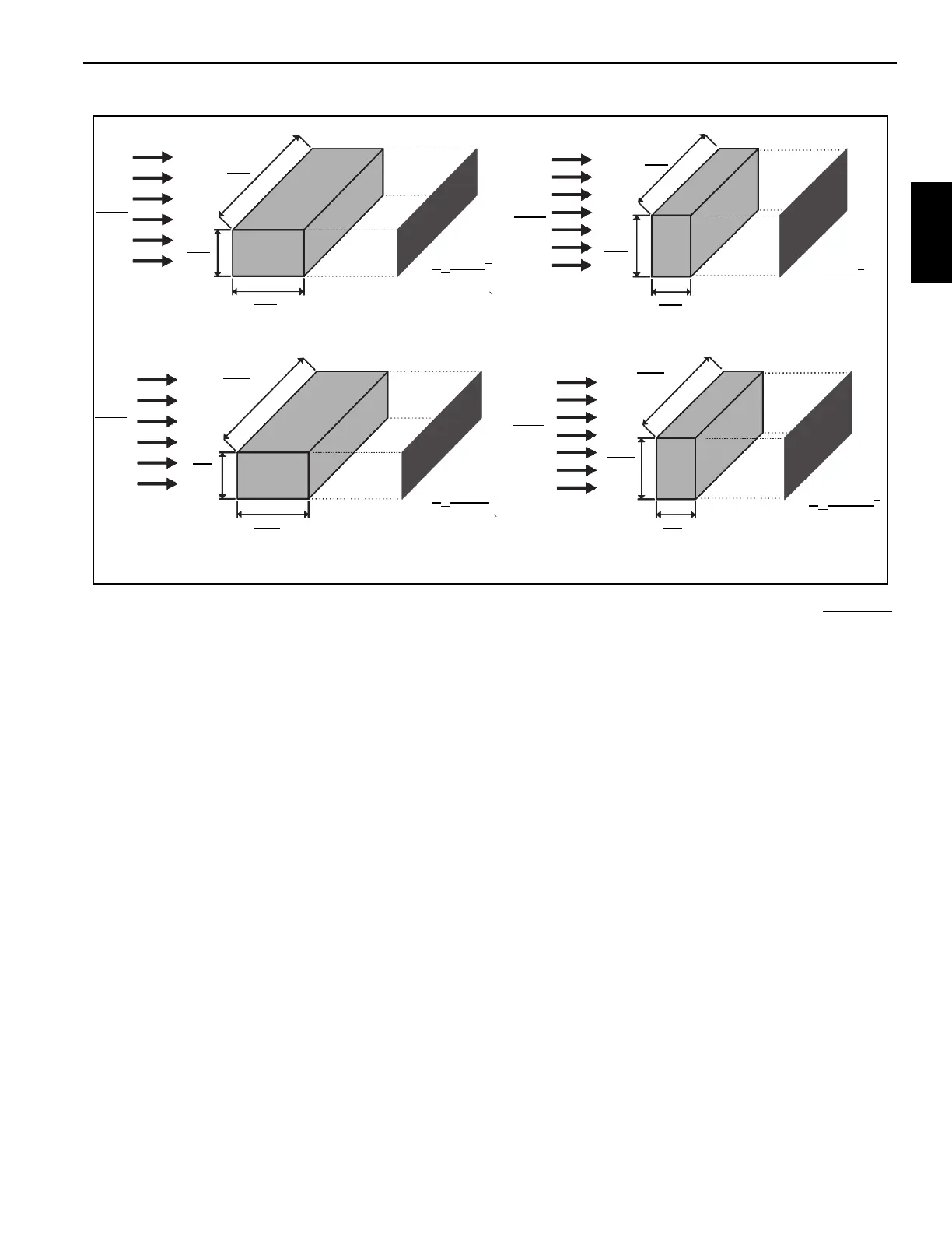
Calculation of Projected Wind Area (Ap):
Determining Wind Drag Coefficient (Cd)
Table 2-2 shows the typical Shapes and corresponding Wind
Drag Coefficient (Cd) values.
If the exact Wind Drag Coefficient of a shape is not known
,
use the maximum value of the shape’s range
(Table 2-2).
If the wind drag coefficient of the load cannot be estimated or
determined, it shall be assumed that (Cd)=2.4.
A
p
=24m
2
A
p
=8m
2
Wind
Wind
8m
1m
3m
8m
1m
3m
A
p
= 250 ft
2
A
p
=75ft
2
Wind
Wind
25 ft
3ft
10 ft
25 ft
3ft
10 ft
8384-1
FIGURE 2-2

Table of Contents

Other manuals for Manitowoc National Crane NBT40 Series

Questions and Answers:

Question and Answer IconNeed help?

Do you have a question about the Manitowoc National Crane NBT40 Series and is the answer not in the manual?

Manitowoc National Crane NBT40 Series Specifications

General IconGeneral
BrandManitowoc
ModelNational Crane NBT40 Series
CategoryConstruction Equipment
LanguageEnglish

Related product manuals