National Crane Published 4-23-2018 Control # 239-11 4-5
NBT40 SERIES OPERATOR MANUAL SET-UP
14. Using boom telescope function, slowly retract boom.
The jib stow bracket (H, Figure 4-1) on the side of the jib
will engage the side stow bracket (D) on the side of the
1
st
section boom; first lifting the jib and then engaging
the jib side stow bracket (H) and the stow bracket (D)
completely upon full retraction of the boom.
15. Install stow pin (A, Figure 4-1) with spring clip into the jib
stow bracket (H) on the jib. Complete engagement of
stow brackets and proper installation of pin A is critical
for secure jib stow attachment.
16. Remove pins (C1 Figure 4-1) from upper and lower jib
ears. A slight hammer strike may be necessary to
remove pins. Always use proper eye protection during
this step.
17. Reinstall loadline over boom sheave case.
JIB REMOVAL
Should jib removal from the boom become necessary,
proceed as follows:
1. Unstow and swing jib into position on the boom tip
according to Steps 1 - 10 in the preceding jib deployment
section.
2. Support and raise the jib at its balance point and remove
the two swing around pins. Jib is now free of boom.
3. To install, proceed in reverse order of removal.
When the jib is stowed on side of crane, always leave the
ram and handle sleeve of the jib jack pushed all the way
down to reduce exposure to rusting.
Jib Maintenance
1. Lubricate as outlined in SECTION 5.
2. Check for free rotation of jib sheave daily when using jib.
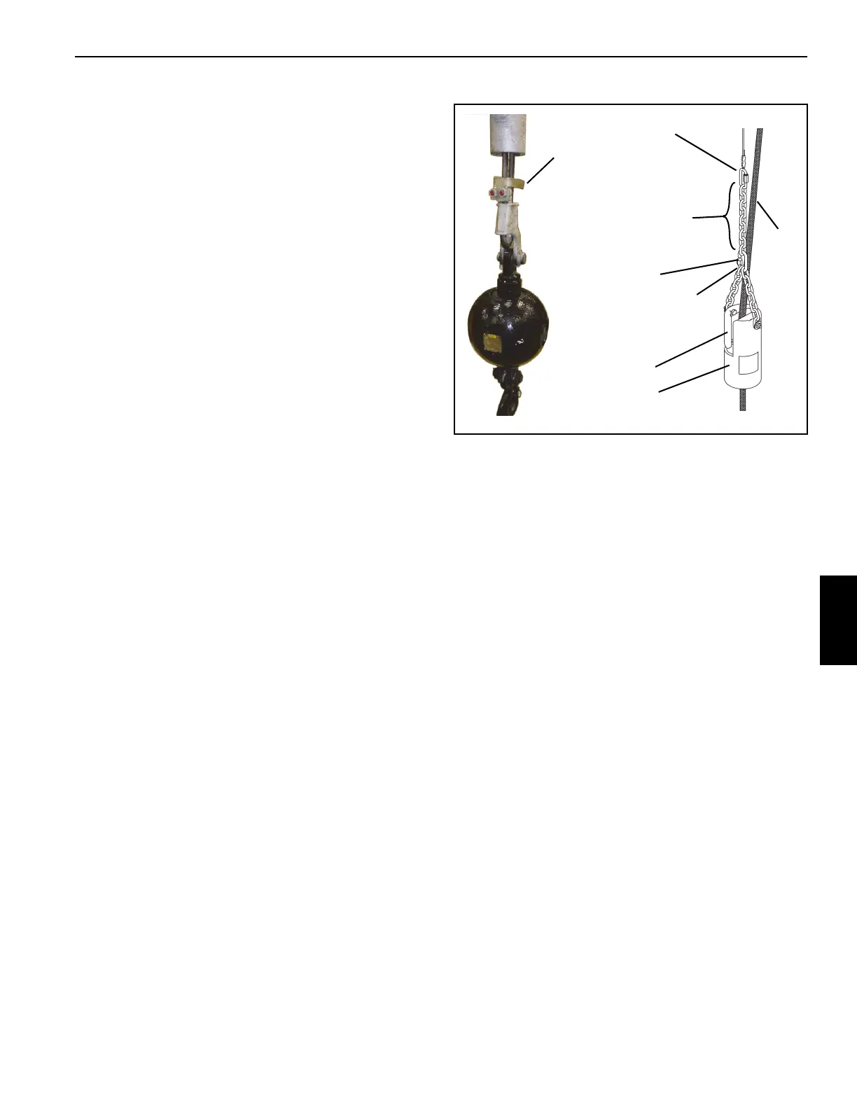
ANTI-TWO BLOCK WEIGHT INSTALLATION
To prevent the hoist cable from slipping out of the ant-two-
block weight, rig the weight as shown in Figure 4-2.
The A2B bracket is for single part line use only. Remove the
A2B bracket shown in Figure 4-2 from the hoist cable when
changing from a single part line to a multiple part line to allow
the hoist cable and wedge socket to reeve through the
sheaves on the boom nose and the hookblock. Re-install the
clamp and nuts to the cable before performing a lift.
MULTI-PART LINE REEVING
Multi-part line reeving enables greater loads to be lifted than
can be lifted with single part line. However, loads are limited
by the stability and structural integrity of the crane. The load
must be within the limits contained in the load chart.
Using Multiple Part Lines
The hoist data chart provides information for pull limitations
on the hoist with various multipart reevings. These ratings
are based on providing the proper operating safety factor on
the cable supplied with the crane. Therefore, any
replacement rope must meet the cable specification in this
manual.
The A2B bracket is for single part line use only. Remove the
A2B bracket shown in Figure 4-2 from the hoist cable when
changing from a single part line to a multiple part line to allow
the hoist cable and wedge socket to reeve through the
sheaves on the boom nose and the hookblock. Re-install the
clamp and nuts to the cable before performing a lift.
STOW PEGS FOR HOIST CABLE
Stow pegs located on top of the boom keep the hoist cables
secure when not reeved over the boom nose. The main hoist
cable is stowed on the right peg and the auxiliary hoist cable
is stowed on the left peg as viewed from the back of the
boom.
FIGURE 4-2
The anti-two-block chain
must be installed
between the slot in the
weight and the hoist
cable.
Anti-two Block
Weight
Hoist
Cable
Slot
Chain Length 40 cm
(16 inches) Do not
shorten the chain.
Upper Link
Lower Link
The A2B bracket must be
removed from the hoist
cable when reeving for
multi-part line.
8835

 Loading...


