EasyManua.ls Logo

Manitowoc S600M - User Manual

Manitowoc S600M
103 pages
To Next Page IconTo Next Page
Loading...
Thank you for selecting a Manitowoc Ice Machine, the dependability leader in ice making equipment and related products.
With proper installation, care and maintenance, your new Manitowoc Ice Machine will provide you with many years of
reliable and economical performance.
S600M Model
Ice Machines
Service
Manual
Part Number 80-1630-3
9/2004
This manual is updated as new information and models
are released. Visit our website for the latest manual.
www.manitowocice.com

Table of Contents

Other manuals for Manitowoc S600M

Question and Answer IconNeed help?

Do you have a question about the Manitowoc S600M and is the answer not in the manual?

Manitowoc S600M Specifications

General IconGeneral
BrandManitowoc
ModelS600M
CategoryIce Maker
LanguageEnglish

Summary

Safety and Procedural Notices

Warning Notices

Alerts to potential personal injury.

Caution Notices

Alerts to potential machine damage.

Important Procedural Information

Provides useful extra information for procedures.

Read Before Proceeding

Emphasizes reading important instructions.

Section 1 General Information

Model Identification and Coding

Lists models and explains number coding.

Ice Cube Dimensions

Shows dimensions of dice and half dice.

Lifting Safety Warning

Personal injury potential during lifting/installing.

Accessories

Guardian Sachet Packets

Inhibits bacteria and slime growth.

Manitowoc Cleaner and Sanitizer

Approved cleaning and sanitizing solutions.

Model and Serial Number Location

Warranty Information

Warranty Coverage Details

Details parts, labor, and exclusions.

Authorized Warranty Service Requirements

Requirements for warranty repair.

Section 2 Installation Instructions

General Installation Guidance

Instructions for qualified installers.

Ice Machine Dimensions

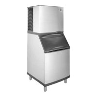
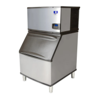
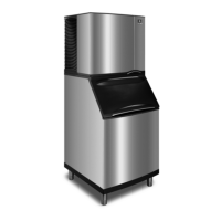
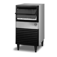
Provides physical dimensions of the ice machine.

Warranty Impact Warning

Failure to follow guidelines affects warranty.

Location Requirements

Ice Machine Heat of Rejection

Heat rejected by the machine for AC sizing.

Freezing Temperature Warning

Protect from freezing temperatures.

Electrical Service Requirements

Wiring and Grounding Codes

Wiring must conform to codes.

Voltage and Ampacity Specifications

Specifies voltage variation & circuit ampacity.

Electrical Wiring Connections

Diagram Purpose Warning

Diagrams are for connections, not routing.

UK Wiring Color Guidance

Wiring color code guidance for UK.

Water Supply and Drain Requirements

Water Inlet Line Guidelines

Guidelines for connecting water inlet lines.

Heat Application Warning

Do not apply heat to valve fitting.

Drain Connection Guidelines

Guidelines for drain line installation.

Water Supply and Drain Line Sizing

Plumbing Code Compliance

Plumbing must conform to codes.

Installation Check List

Before Starting the Ice Machine

Personal Injury Warning

Potential personal injury from misuse.

AuCS Automatic Cleaning System

Info on the optional cleaning system.

Section 3 Ice Machine Operation

Component Identification

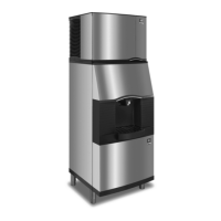
Labels key parts of the ice machine.

Sequence of Operation

Initial Start-Up Procedures

Steps for initial and post-shutoff start.

Freeze Sequence Steps

Details the freeze cycle steps.

Harvest Sequence

Automatic Shut-Off Description

Describes how the machine shuts off.

Safety Timers Explained

Explains built-in safety timers.

Warm Water Rinse Cycle

Details the automatic rinse cycle.

Operational Checks

Water Level Check Procedure

How to check and maintain water level.

Ice Thickness Adjustment

How to check and adjust ice thickness.

Harvest Sequence Water Purge

Water Purge Adjustment Procedure

Adjustment for water purge settings.

Power Disconnect Warning

Disconnect power before proceeding.

Section 4 Maintenance

General Maintenance Overview

Maintenance is not covered by warranty.

Ice Machine Inspection Guide

Checks for leaks and airflow.

Water-Cooled Condenser Issues

Symptoms of condenser issues.

Maintenance Safety Warning

Call service if procedures are not understood.

Guardian System Maintenance

Sachet Replacement Frequency

When to replace Guardian sachets.

Sachet Replacement Steps

Steps for replacing sachets.

Damaged Sachet Cleanup Procedure

Steps for cleaning up spills.

Interior Cleaning and Sanitizing

Cleaning Procedure Steps

Steps for cleaning the ice machine.

Approved Solutions Warning

Use approved cleaner/sanitizer.

Chemical Handling Safety

Wear safety gear when handling chemicals.

Sanitizing Procedure

Ice Evaporator Caution

Do not force ice from evaporator.

Power Disconnect for Sanitizing

Disconnect power before proceeding.

Part Removal for Cleaning

Power and Water Disconnect Warning

Disconnect power and water supply.

Cleaner;Sanitizer Mixing Warning

Do not mix cleaner/sanitizer.

Water Pump Immersion Caution

Do not immerse water pump motor.

Water Curtain Removal

Ice Thickness Probe Removal

Power Disconnect for Probe Maintenance

Disconnect power before proceeding.

Water Distribution Tube Removal

Water Spray Warning

Disconnect power and water supply.

Water Trough Removal

Water Level Probe Maintenance

Power Disconnect for Probe Maintenance

Disconnect power before proceeding.

Water Pump Maintenance

Power;Water Disconnect for Pump Maintenance

Disconnect power and water supply.

Water Dump Valve Maintenance

Power;Water Disconnect for Valve Maintenance

Disconnect power and water supply.

Dry Parts Before Assembly

Ensure parts are dry before assembly.

Water Inlet Valve Maintenance

Power;Water Disconnect for Valve Maintenance

Disconnect power and water supply.

Removal from Service;Winterization

Freezing Damage Warning

Damage from freezing is not covered by warranty.

Section 5 Before Calling For Service

Troubleshooting Checklist

Troubleshooting guide for common problems.

Safety Limit Feature

Problem Cause and Correction Guide

Lists common issues, causes, and solutions.

Section 6 Electrical System

Energized Parts Charts Overview

Charts showing energized parts in operation cycles.

Safety Timers Explained

Details non-adjustable safety timers.

Wiring Diagram Sequence of Operation

Water Purge Sequence Details

Explains the water purge step.

Water Purge Operation Table

Table detailing water purge operations.

Sequence of Operation Steps

Refrigeration System Start-Up

Details the start-up process.

Pre-Chill Sequence

Details the pre-chill steps.

Freeze Sequence

Details the freeze steps.

Water Purge Sequence

Details the water purge steps.

Harvest Sequence

Details the harvest steps.

Automatic Shut-Off Sequence

Details the auto shut-off steps.

Wiring Diagrams Overview

Wiring Diagram Legend

Explains symbols used in diagrams.

Electrical Work Safety

Always disconnect power before working on circuitry.

S600 M - Single Phase Wiring Diagram

Component Specifications and Diagnostics

Main Fuse Function and Check

Function, specs, and check procedure.

High Voltage Warning

High voltage applied to control board.

Bin Switch Function and Operation

Function, specs, and operation.

Ice Making Start Condition

Water curtain must be on to start ice making.

Bin Switch Symptoms and Diagnostics

Bin Switch Failure Modes

Symptoms of open or closed switch failures.

Bin Switch Continuity Test

Procedure to test bin switch continuity.

Compressor Electrical Diagnostics

Resistance and Ground Checks

Resistance test and ground checks.

Diagnosing a Seized Compressor

Tests to diagnose a seized compressor.

Diagnosing Capacitors

How to diagnose capacitor issues.

PTCR Diagnostics

What is a PTCR?

Explains PTCR function and use.

Compressor Start Sequence with PTCR

Details the PTCR's role in starting.

Troubleshooting PTCRs

PTCR Failure to Start Compressor

Reasons for PTCR failure.

Checking the PTCR

PTCR Inspection and Testing

Visual inspection and resistance measurement.

Power Disconnect for PTCR Check

Disconnect electrical power before proceeding.

Diagnosing Start Components

Capacitor and Relay Checks

How to diagnose capacitor and relay issues.

Toggle Switch Check Procedure

Steps to check toggle switch operation.

Electronic Control Board Overview

Control Board General Information

Control Board Safety Limits

Built-in safety limits for component protection.

Understanding Control Board Inputs

How inputs affect control board operation.

Ice Thickness Probe Function

How the Ice Thickness Probe Works

Explains the sensing circuit.

Ice Thickness Check and Adjustment

Factory set thickness and adjustment.

Freeze Time Lock-In Feature

Prevents short cycling.

Maximum Freeze Time Safety

Safety feature for maximum freeze duration.

Ice Thickness Probe Cleaning

Procedure for cleaning the probe.

Diagnosing Ice Thickness Control Circuitry

Troubleshooting Harvest Initiation Failure

Steps for harvest initiation failure.

Troubleshooting Premature Harvest

Steps for premature harvest.

Water Level Control Circuitry

Water Level Probe Light Function

Monitoring water level via light.

Water Inlet Valve Safety Shut-Off

Feature limits inlet valve on-time.

Freeze Cycle Water Level Control

How water level controls freeze cycle.

Harvest Cycle Water Purge Adjustment

Harvest cycle water purge adjustment.

Diagnosing Water Level Control Circuitry

Troubleshooting Water Trough Overfilling

Troubleshooting overfilling.

Diagnostic Restart Procedure

Restart procedure for diagnostics.

Troubleshooting Water Not Entering Trough

Diagnostic Restart Procedure

Restart procedure for diagnostics.

Diagnosing Machine Not Running

Power and Component Checks

Steps to check power and components.

Control Board Replacement Considerations

When to replace the control board.

S600 M - Single Phase Terminal Board Wiring Diagram

Section 7 Refrigeration System

Sequence of Operation Overview

Explains system operation.

Prechill and Freeze Cycle Diagram

Diagram for prechill/freeze cycles.

Prechill Refrigeration Process

Details the prechill process.

Freeze Cycle Refrigeration Process

Details the freeze process.

Harvest Cycle Diagram

Harvest Cycle Refrigeration Process

Details the harvest process.

Operational Analysis and Diagnostics

General Diagnostic Principles

Importance of understanding malfunctions.

Misdiagnosis Examples

Illustrates misdiagnosis scenarios.

Before Beginning Service

Pre-Service Questions

Key questions for initial diagnosis.

Ice Production Check Procedure

Procedure to check ice production.

Installation and Visual Inspection Checklist

Water System Checklist

Ice Formation Pattern Analysis

Normal Ice Formation Description

Describes normal ice formation.

Thin Ice at Evaporator Outlet

Describes thin ice at outlet.

Thin Ice at Evaporator Inlet

Spotty Ice Formation

No Ice Formation

Safety Limits Overview

General Safety Limit Function

Built-in safety limits for component protection.

Safety Limit #1 and #2 Details

Freeze and harvest time limits.

Safety Limit Indication Methods

How safety limits are indicated.

Analyzing Safety Limit Triggers

Reasons for safety limits tripping.

Safety Limit #1 Troubleshooting

Safety Limit #1 Possible Causes

Lists potential causes for Safety Limit #1.

Safety Limit #1 Corrective Actions

Actions to correct Safety Limit #1 causes.

Safety Limit Notes

Notes on safety limit codes and indications.

Safety Limit #2 Troubleshooting

Safety Limit #2 Possible Causes

Lists potential causes for Safety Limit #2.

Safety Limit #2 Corrective Actions

Actions to correct Safety Limit #2 causes.

Safety Limit Notes

Notes on safety limit codes and indications.

Analyzing Discharge Pressure

Discharge Pressure Procedure

Steps for analyzing discharge pressure.

High Discharge Pressure Checklist

Troubleshooting high discharge pressure.

Low Discharge Pressure Checklist

Troubleshooting low discharge pressure.

Analyzing Suction Pressure During Freeze Cycle

Suction Pressure Procedure

Steps for analyzing suction pressure.

High Suction Pressure Checklist

Troubleshooting high suction pressure.

Low Suction Pressure Checklist

Troubleshooting low suction pressure.

High Suction Pressure Checklist

High Suction Pressure Causes

Lists potential causes for high suction pressure.

High Suction Pressure Corrections

Actions to correct high suction pressure.

Low Suction Pressure Checklist

Low Suction Pressure Causes

Lists potential causes for low suction pressure.

Low Suction Pressure Corrections

Actions to correct low suction pressure.

Evaporator Inlet and Outlet Temperatures

Temperature Comparison Notes

Clarifies procedure applicability and sensor placement.

Harvest Valve Temperature Check

Harvest Valve Temperature Procedure

Steps to check harvest valve temperature.

Harvest Valve Temperature Notes

Notes on feeling valve outlet vs. inlet.

Hot Surface Warning

Caution about hot surfaces.

Discharge Line Temperature Analysis

Temperature Analysis Procedure

Steps for analyzing discharge line temperature.

Using Refrigeration System Operational Analysis Tables

General Table Usage

How to use tables with charts and checklists.

Using the Analysis Procedure

Step-by-step guide for using analysis tables.

Final Analysis Interpretation

How to interpret analysis table results.

Column 1: Harvest Valve Leaking

Identifying harvest valve leaks.

Column 2: Low Charge;TXV Starving

Identifying low charge/starving TXV.

Column 3: TXV Flooding

Identifying TXV flooding.

Column 4: Compressor Issues

Compressor related issues.

Refrigeration System Operational Analysis Tables

Ice Production Analysis Factors

Factors affecting ice production.

Installation and Water System Checks

Correcting installation/water issues.

Ice Formation Pattern Analysis

Analyzing ice formation patterns.

Safety Limits Analysis

Analyzing safety limit trips.

Discharge Pressure Analysis

Analyzing discharge pressure.

Suction Pressure Analysis

Analyzing suction pressure.

Evaporator Temperature Comparison

Evaporator temperature comparison.

Compressor;Harvest Valve Temp Comparison

Compressor/harvest valve temp comparison.

Discharge Line Temperature Recording

Recording discharge line temperature.

Final Analysis Interpretation

Interpreting the analysis results.

Pressure Control Specifications and Diagnostics

High Pressure Cut-Out (HPCO) Control

Function, specs, and check procedure.

HPCO Failure to Cut-Out Warning

Action if HPCO fails to cut out.

Cycle Time and Pressure Charts

Cycle Time Calculations

Formulas for cycle time calculation.

24 Hour Ice Production Charts

Charts for ice production.

Operating Pressures Charts

Charts for operating pressures.

Refrigerant Recovery, Evacuation, and Recharging

Standard Recovery;Evacuation Procedures

Standard procedures for recovery/evacuation.

Manifold Gauge Connections

Instructions for manifold gauge connections.

Contaminated Refrigerant Warning

No responsibility for contaminated refrigerant use.

Liquid Line Drier Replacement Note

Replace liquid line drier before evacuating.

Self-Contained Charging Procedures

Proper Charge Criticality

Criticality of proper charge.

Recovery;Evacuation Connections Diagram

Remote Charging Procedures

Post-Charging Steps

Post-charging steps.

Remote Charging Connections Diagram

System Contamination Clean-Up

General Clean-Up Requirements

Requirements for restoring contaminated systems.

Determining Contamination Severity

How to determine contamination severity.

Contamination;Cleanup Chart

Chart linking symptoms to cleanup procedures.

Mild System Contamination Cleanup Procedure

Dry Nitrogen Recommendation

Dry nitrogen recommended for evacuation.

Severe System Contamination Cleanup Procedure

Refrigerant Sweeps Warning

Refrigerant sweeps not recommended.

Replacing Pressure Controls Without Refrigerant Charge Removal

In-Warranty Repair Requirement

Required for in-warranty repair.

Component Replacement Warning

Do not unsolder defective components.

Using Pinch-Off Tool Diagram

Filter-Driers Importance

Filter-Drier Warranty and Replacement

Driers are warranty parts, replace when opened.

Total System Refrigerant Charges

Verifying Refrigerant Charge

Refer to serial tag for accurate charge.

Refrigerant Definitions

Recover vs. Recycle vs. Reclaim

Definitions of refrigerant handling terms.

Refrigerant Re-Use Policy

Approved Refrigerant Types

Requirements for new, reclaimed, and recovered refrigerant.

Contaminated Refrigerant Responsibility

No responsibility for contaminated refrigerant use.

HFC Refrigerant Questions and Answers

Compressor Oil Requirements

Required compressor oil type.

POE Oil Characteristics and Implications

Characteristics and implications of POE oils.

HFC Leak Checking and Charging

Methods for HFC leak checking and charging.

HFC Refrigerant Recovery Regulations

Regulations on HFC recovery.

Manitowoc Factory Service School

Improve Service Techniques

Benefit of attending service school.

Training Details and Inclusions

Duration, content, and inclusions of training.

Obtaining School Information

How to get more information and dates.

Related product manuals