Refrigeration System Section 7
7-2
Part Number 80-1630-3
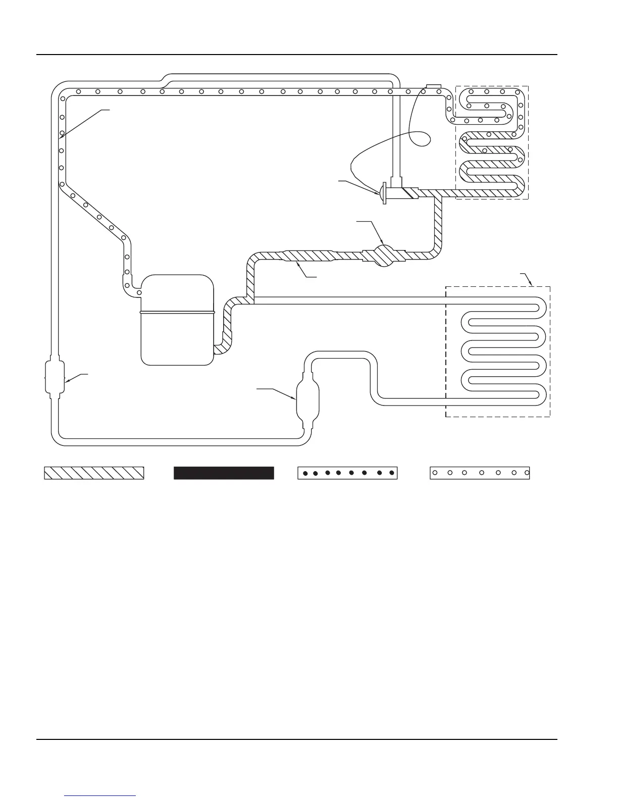
Figure 7-2. Self-Contained Harvest Cycle
Harvest Cycle Refrigeration Sequence
Hot gas flows through the energized harvest valve,
heating the evaporator. The harvest valve is sized to
allow the proper amount of refrigerant into the
evaporator. This specific sizing (along with the proper
system refrigerant charge) assures proper heat transfer,
without the refrigerant condensing and slugging the
compressor.
HEAT
EXCHANGER
EVAPORATOR
CONDENSER
COMPRESSOR
EXPANSION VALVE
HOT GAS SOLENOID VALVE
AIR OR WATER
DRIER
STRAINER
RECEIVER
(WATER COOLED ONLY)
LOW PRESSURE VAPORLOW PRESSURE LIQUIDHIGH PRESSURE LIQUIDHIGH PRESSURE VAPOR
SV1570