
K
Karen HamptonAug 13, 2025
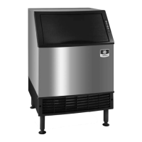
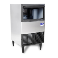
How to troubleshoot a Manitowoc UDE065A that does not operate?
- SSeth HarrisAug 13, 2025
If your Manitowoc Ice Maker isn't operating, there could be several reasons. First, check the power supply: ensure the machine is plugged in, the main switch is on, the breaker hasn't tripped, and the fuse is intact. If power isn't the issue, make sure the ice machine is turned on by pressing the On/Off button. Lastly, confirm that the damper is in the upright position and can swing freely.