Do you have a question about the Manitowoc UDE065A and is the answer not in the manual?
Essential precautions for safe operation, installation, and maintenance.
Criteria for selecting an appropriate and safe installation site.
Details on voltage, fuse/breaker, and ampacity for installation.
Guidelines for connecting water supply and drain lines.
Procedure for cleaning and sanitizing the ice machine interior.
Steps to clean the condenser for optimal performance.
Procedures for safely removing the ice machine from service.
Explanation of the touch pad buttons and their functions for operation.
Detailed steps of the ice making cycle and control board revisions.
Common problems and solutions for specific ice machine models.
Steps to identify why the ice machine is not starting or operating.
Procedure to check the function and resistance of the main fuse.
Steps to diagnose compressor electrical issues and winding resistance.
Procedure to check the function of ice thickness and harvest float switches.
Guidelines to verify correct ice machine operation and performance.
Electrical diagrams illustrating component connections and layout.
Diagrams and component identification for electronic control boards.
Diagrams showing the refrigerant tubing layout for various models.
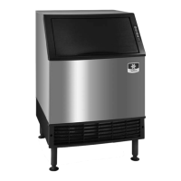
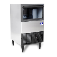
Lists all supported ice machine models covered by the manual.
Criteria for selecting an appropriate and safe installation site.
Details on voltage, fuse/breaker, and ampacity for installation.
Guidelines for connecting water supply and drain lines.
Procedure for cleaning and sanitizing the ice machine interior.
Specific cleaning and sanitizing steps for certain models.
Instructions for cleaning the external surfaces of the ice machine.
Procedures for winterizing air-cooled ice machines.
Procedures for winterizing water-cooled ice machines.
Information on changes and updates to control board versions.
Details on software versions and their functional changes.
Steps for initial machine startup after being shut off.
Explanation of the freeze cycle process.
Explanation of the harvest cycle process.
Conditions causing safety limit 1 shutdown and indicator lights.
Conditions causing safety limit 2 shutdown and indicator lights.
Procedure to inspect and verify ice cube thickness.
Steps to adjust the ice thickness control dial.
Steps for initial machine startup after being shut off.
Steps for starting the refrigeration system.
Explanation of the freeze cycle process.
Steps for initial machine startup after being shut off.
Explanation of the freeze cycle process.
Explanation of the siphon system's function and maintenance.
How to check and verify the correct water level.
A systematic list of common ice machine problems and their causes.
Explanation of the feature preventing short cycling.
Conditions causing safety limit 1 shutdown and indicator lights.
Conditions causing safety limit 2 shutdown and indicator lights.
Important notes regarding safety limit storage and indication.
Checklist for diagnosing safety limit #1 causes.
Checklist for diagnosing high discharge pressure.
Checklist for diagnosing low discharge pressure.
Checklist for diagnosing high suction pressure.
Checklist for diagnosing low suction pressure.
Explanation of the harvest valve's function and normal operation.
Interpreting diagnostic results to identify refrigeration problems.
Steps to diagnose why the UDE065 ice machine will not run.
Expected temperature ranges for normal operation of UDE065.
Interpreting diagnostic data for UDE065 refrigeration system.
Symptoms indicating a flooding expansion valve issue.
Symptoms indicating low refrigerant or starving expansion valve.
Checklist for diagnosing high discharge line temperature.
Checklist for diagnosing low discharge temperature.
Checklist for diagnosing high suction line temperature.
Checklist for diagnosing low suction line temperature.
Explanation of the harvest valve's function and normal operation.
Steps to diagnose why the UDE080 ice machine will not run.
Conditions causing safety limit #1 shutdown and indicator lights.
Conditions causing safety limit #2 shutdown and indicator lights.
Important notes regarding safety limit storage and indication.
Checklist for diagnosing safety limit #1 causes.
Interpreting diagnostic data for UDE080 refrigeration system.
Symptoms indicating a flooding expansion valve issue.
Symptoms indicating low refrigerant or starving expansion valve.
Checklist for diagnosing high discharge line temperature.
Checklist for diagnosing low discharge temperature.
Checklist for diagnosing high suction line temperature.
Checklist for diagnosing low suction line temperature.
Explanation of the harvest valve's function and normal operation.
Procedure to check the function and resistance of the main fuse.
Steps to verify normal operation of the touch pad interface.
How to check the function of float switches.
Procedure to check thermistor resistance and temperature readings.
Steps to check bin thermostat resistance and operation.
Procedure to check liquid line thermistor resistance and temperature.
How to inspect and test the ON/OFF/WASH toggle switch.
Measuring resistance of compressor windings for diagnostics.
Testing compressor motor windings for ground faults.
Steps to check the fan cycle control's operation and pressure settings.
Steps to check the HPCO control's cut-out pressure.
Information on the function and importance of the liquid line filter drier.
Definitions related to refrigerant recovery, recycling, and reclaiming.
Connection points for refrigerant recovery and recharging.
Critical steps for charging refrigerant accurately.
Connection points for refrigerant recovery and recharging.
Methods to determine the level of contamination in the system.
Guidelines to verify correct ice machine operation and performance.
Expected cycle times for UDE065 under various conditions.
Expected ice production rates for UDE065 under various conditions.
Expected cycle times for UDE080 under various conditions.
Expected ice production rates for UDE080 under various conditions.
Normal operating temperature ranges for UDE080 models.
Expected cycle times for U0140/UF0140 models.
Expected ice production rates for U0140/UF0140 models.
Normal operating pressures for U0140/UF0140 models.
Expected cycle times for U0140 water-cooled models.
Expected ice production rates for U0140 water-cooled models.
Normal operating pressures for U0140 water-cooled models.
Expected cycle times for U0190/UF0190 models.
Expected ice production rates for U0190/UF0190 models.
Normal operating pressures for U0190/UF0190 models.
Expected cycle times for U0240/UF0240 models.
Expected ice production rates for U0240/UF0240 models.
Normal operating pressures for U0240/UF0240 models.
Expected cycle times for U0240/UF0240 water-cooled models.
Expected ice production rates for U0240/UF0240 water-cooled models.
Normal operating pressures for U0240/UF0240 water-cooled models.
Expected cycle times for U0310/UF0310 models.
Expected ice production rates for U0310/UF0310 models.
Normal operating pressures for U0310/UF0310 models.
Expected cycle times for U0310/UF0310 water-cooled models.
Expected ice production rates for U0310/UF0310 water-cooled models.
Normal operating pressures for U0310/UF0310 water-cooled models.
Electrical diagrams illustrating component connections and layout.
Diagrams and component identification for electronic control boards.
Diagrams showing the refrigerant tubing layout for various models.
Diagram and component list for UF model control boards.
Diagram and component list for U models with J4 thermistor.
Diagram and component list for U models prior to thermistor terminal.
Diagram and component list for UDE065 control board.
Diagram and component list for UDE080 control board.
Schematic illustrating the tubing layout for UDE065 models.
Schematic for UDE080/U0140/UF0140 tubing layout.
Schematic for U0190/UF0190/U0240/UF0240/U0310/UF0310 tubing layout.