EasyManua.ls Logo

Manley CORE - User Manual

Manley CORE
16 pages
Print Icon
To Next Page IconTo Next Page
Loading...
MAX
MIN
COMPRESSION
IN
BYPASS
F
AST
ATT
ACK
SLOW FAST
COMP
R
E
S
S
OR
SLOW
FREQUENCY
100Hz-1kHz
1kHz-10kHz
0
-10 +10
dB
LOW
0
0
-12
+12
dB
MIN MAX
E
Q
HI
0
-12 +12
dB
LIMIT
MAX
MIN
LIMITING
RELEASE
RELEASE
SLOW F
AST
OUTPUT
GAIN
-6
+4
dB
LI
MI
TER
c
o
r
e
O/P 1 GR
O/P 2
REFERENCE
CHANNEL S
TRIP
INPUT
LEVEL
MIC
MIC
FLAT
0
180
120Hz
HI
LOW
LINE
PH
A
N
TO
M
4
8V
HA
NDC
RA
FTED
IN C
AL
IFO
R
N
I
A
USA
DIRECT IN
MANLEY LABORATORIES INC.
13880 MAGNOLIA AVE. CHINO, CA 91710
PHONE +1 (909) 627-4256
service@manleylabs.com
www.manley.com
MAINS VOLTAGE SHOWN ON SERIAL TAG WARNING: TO REDUCE THE RISK OF FIRE OR
ELECTRIC SHOCK, DO NOT EXPOSE THIS UNIT TO RAIN OR MOISTURE CAUTION: RISK OF
ELECTRIC SHOCK. DO NOT OPEN. REFER SERVICING TO QUALIFIED PERSONNEL ONLY.
INSTRUMENT
IN
BRICKWALL
LIMITER
MIC IN
DIRECT
OUT 1
MAIN
OUT 2
HP
FILTER
LINE IN
PHASE
OUTPUT
GAIN
TUBE STAGE
EQ
DI
STAGE
LINE
STAGE
COMPRESSOR
®
ATTENUATOR
INSERT
JACK
FET
MIC INPUT
LINE INPUT
DIRECT OUTPUT (1)
INSERT
MAIN OUTPUT (2)
PIN1: SHIELD/GROUND
PIN2: HOT/POSITIVE PHASE
PIN3: LOW/NEGATIVE PHASE
XLR PINOUT
TIP: SEND
RING: RETURN
SLEEVE: GROUND
c o r e
REFERENCE CHANNEL STRIP
OPERATIONAL BLOCK DIAGRAM
HAND CRAFTED IN USA
SERIAL No.
REFERENCE CHANNEL STRIP
c o r e
c o r e
c o r e
OWNER’S MANUAL
R

Other manuals for Manley CORE

Question and Answer IconNeed help?

Do you have a question about the Manley CORE and is the answer not in the manual?

Summary

Introduction and Manual Information

An Introduction to the Manley CORE

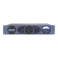
Overview of the CORE's design goals and features.

Manual Conventions Explained

Explains symbols and conventions used throughout the manual.

Safety and Initial Setup

Important Safety Instructions

Lists critical safety warnings for water, heat, power sources, and servicing.

Getting Started Guide

Instructions for unpacking, checking components, and initial setup.

Front Panel Controls

Input Section Operation Details

Details the input attenuator, source select, HPF, gain, phantom power, and phase.

Core Calibration Procedure

VU Meter Calibration Steps

Steps to calibrate the VU Meter for OP1 and GR zero set.

ELOP Compressor Calibration

Procedure to adjust compressor gain reduction and meter GR.

Peak Limiter Calibration Steps

Steps to calibrate the peak limiter reference voltage and LED indicators.

Manley CORE Specifications

General IconGeneral
TypeChannel Strip
CompressorYes
EqualizerYes
De-esserYes
Power SupplyExternal Power Supply
Channels1
EQ3-band
PreampYes
OutputBalanced XLR
InputsXLR, 1/4"
OutputsXLR, 1/4"
Tube12AX7

Related product manuals