VR12
VR16
Diagram 8
Diagram 9
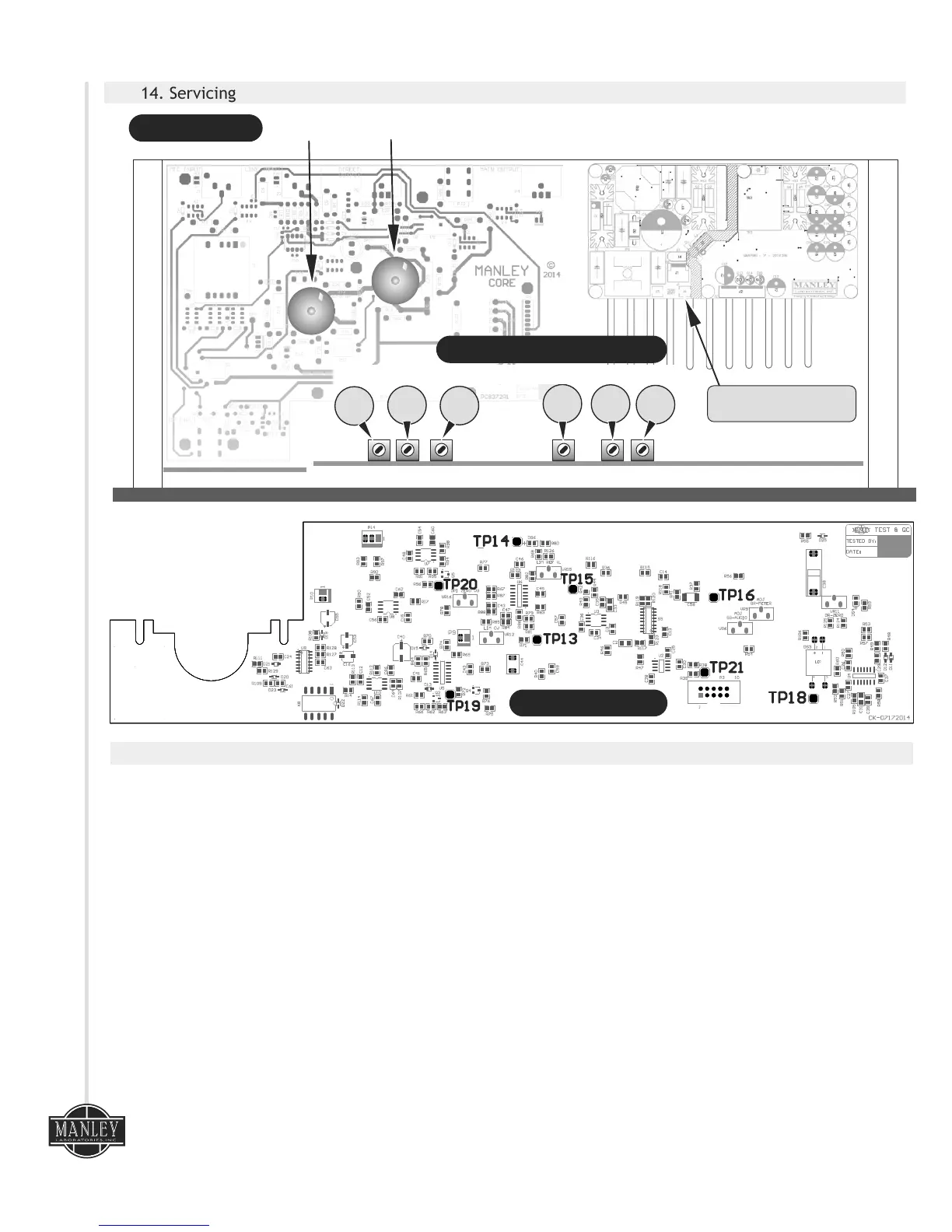
14. Servicing
VR11
VR9
VR6
12AX7WA
6922
TUBE LOCATION
CALIBRATION TRIM POT LOCATION
c o r e
11
TEST POINT LOCATION
VR15
GR-ZERO
GR-METER
GR-AUDIO
2 Amp Slow-Blow (T)
20mm Ceramic FUSE
LIM CV
LIM REF V
OP1 ZERO VU
15. Core Calibration Procedure
The CORE requires calibration for 3 sections of its circuitry:
I) VU METER- Adjust: +4dBu (1.228 Volts RMS) = “0” VU, Meter “GR” zero set
®
ii) ELOP COMPRESSOR - Adjust: Gain Reduction (Audio & Meter GR)
iii) FET PEAK LIMITER - Adjust: reference voltage & FET control voltage
Tools required:
- Audio Tone Generator (oscillator)
- Audio Analyzer or a voltmeter capable of reading both DC & AC voltages.
Initial settings:
- Mic/Line Input select switch: Out = LINE IN Enable
- 120Hz HP filter switch: Out = Disable
- Gain switch: Out = LOW
- 48V Phantom switch: Out = OFF
- Phase Invert switch: Out = 0
- Input Level Attenuator: Set at Minimum
- Compressor Section: Switch = Bypass; Compression = MAX, Attack & Release = FAST
- Shelving EQ section: High/Low controls set both = 12:00 o'clock.
- Mid EQ section: Boost/Cut control = 12:00 O'clock, Frequency range select switch = 100Hz-1kHz,
Frequency sweep control = MIN
- Peak Limiter section: Limiting = MIN, Release = 12:00 o'clock
- Output Gain Control: 12:00 o'clock