3
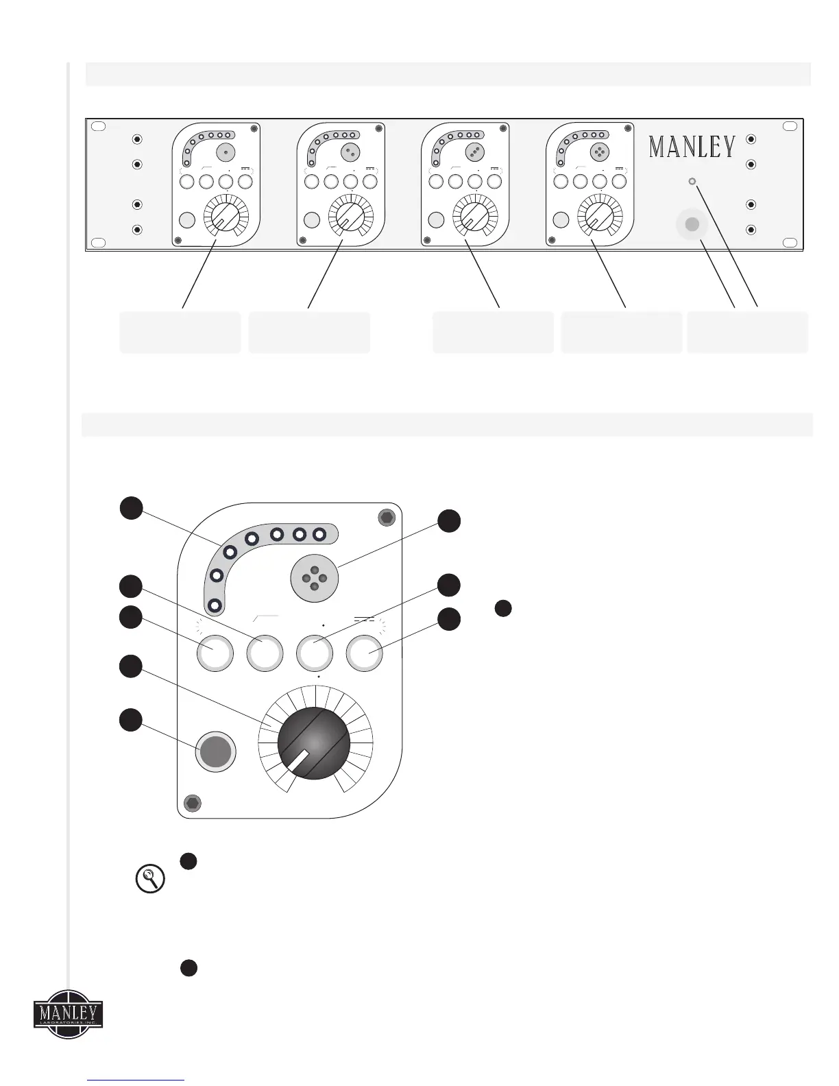
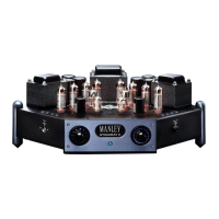
3. Front Panel
4. System Controls
Diagram 2
Diagram 1
4
f o r c e
180120Hz 48V
FLAT
0
HI
LOW PHANTOM
DIRECT IN
INPUT
LEVEL
180120Hz 48V
FLAT
0
HI
LOW PHANTOM
DIRECT IN
INPUT
LEVEL
180120Hz 48V
FLAT
0
HI
LOW PHANTOM
DIRECT IN
INPUT
LEVEL
180120Hz 48V
FLAT
0
HI
LOW PHANTOM
DIRECT IN
INPUT
LEVEL
f o r c e
FO UR C HA NN EL V ACU UM T UB E
M IC ROP HO NE PR EA MP LI FI ER
HANDCRAFTED IN CALIFORNIA USA
CHANNEL 1
CHANNEL 2
CHANNEL 3 CHANNEL 4
POWER SWITCH
& LED
The controls for each channel are identical to
each other. When the push button switches are
engaged and illuminated the top row of switch
labels are in operation.
PEAK LEVEL METER - The seven LED Peak
Level Meter indicates that signal is present. The
first green LED illuminates when there is a signal
greater than -20dBu. The first yellow LED
illuminates when the signal is greater than
+17dBu. The last red LED illuminates when the
signal level reaches +24dBu. This peak red LED
acts as an aid so the user does not overload the
next stage in the chain, as +10dB of headroom is
still available in the FORCE after this LED is lit.
180120Hz 48V
FLAT
0
HI
LOW PHANTOM
DIRECT IN
INPUT
LEVEL
HI / LOW GAIN -
20dB of gain) to the circuit when engaged. For most applications, this switch can be in the LOW
position, but for low output microphones or quiet sources, extra gain may be needed. (Note: If the
internal 20dB jumper is used, noise floor will also increase.)
HIGH PASS FILTER - The 120Hz high pass filter position is useful for reducing breath “pops,” or
any time a reduction of low frequencies such as air conditioning rumble or stage rumble.
The HI/LOW gain switch adds 10dB of gain (or when the internal jumper is set,
1
4
5
3
2
6
7
8
1
2