7. Operational Notes
MIC INPUT: This is a transformer balanced, microphone input to the preamplifier.
The pinout is PIN 1: Ground, PIN 2: HOT (+), PIN 3: COLD(-).
All pins must be connected. DO NOT “float” PIN 2 or PIN 3.
OUTPUTS 1 -4 : Are impedance balanced outputs directly after the tube gain stage. The pinout is PIN
1:Ground, PIN 2: HOT (+), PIN 3: COLD(-). An unbalanced input can be connected with PIN3 grounded or
open/floated.
DIRECT IN 1-4 (ON FRONT PANEL): This is an unbalanced input.
PEAK LEVEL METER
The Peak Level Meter is designed to show that signals are present. This meter is connected on the
output of the preamplifier not the input. As there are only seven LED’s across the range of the meter
this only indicates approximate signal level. If higher resolution for level indiction is required a
secondary meter is recommended on your DAW or mixer.
Getting the most from your FORCE
There is no rule that says you can't put a line-level signal in the Mic input. Try it! Many different
transformer or tube saturation effects can be made this way. The transformer coupled input won’t be
damaged. If you are using an unbalanced signal then PIN 3 must be grounded otherwise the signal will
not pass through the transformer.
Just be careful not to engage the PHANTOM power 48V switch if you have anything other than a
phantom-powered microphone plugged into the MIC INPUT.
®
!
9
f o r c e
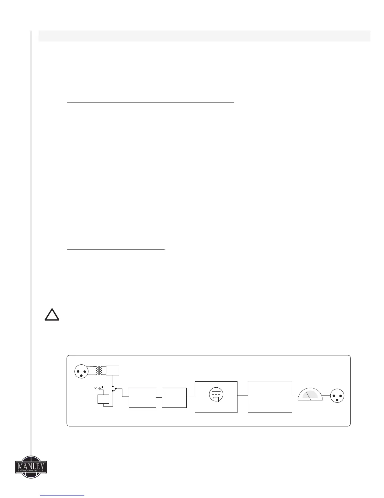
OPERA
TIONAL BLOCK DIAGRAM (ONE CHANNEL)
INSTRUMENT
IN
MIC IN
HP
FILTER
PHASE
DI
STAGE
ATTENUATOR
TUBE STAGE
DISCRETE
output
BUFFER
stage
PEAK LEVEL
METER
OUTPUT