Do you have a question about the Maple Systems HMI5070L and is the answer not in the manual?
Important precautions to prevent damage from electrostatic discharge.
Warning against operating HMIs in areas with flammable gases, vapors, or dusts.
Warning against connecting the HMI to an AC power source.
Mandatory inclusion of a hard-wired EMERGENCY STOP.
Caution on using DC power supplies that do not meet HMI requirements.
Warning against using DC power supplies for inductive loads.
Guidelines for routing HMI cables away from AC voltage and control lines.
Specify +24 VDC ±20% output power supply for HMI.
Use a dedicated regulated DC supply and consider input power line filtering.
Do not use HMI power supply for relays, solenoids, or active devices.
Ensure good, high-integrity earth ground for safety and shielding.
Route all ground wires to a central earth ground point.
Connect HMI chassis ground to panel with braided cable (#14 AWG).
Connect power cable shield wire to HMI chassis ground terminal.
Run DC ground wire directly back to power supply signal return.
Tighten clamps uniformly until snug, avoiding overtightening.
Caution regarding ground loops via USB connection and recommended cable.
HMI must have a unique IP address on the same subnet as the PC.
Steps to configure IP addresses for both Ethernet ports.
LAN1 and LAN2 must be on separate subnets to operate simultaneously.
Steps to enable and configure Wi-Fi via System Settings.
Steps to select and connect to a Wi-Fi network.
When using Wi-Fi and Ethernet simultaneously, ensure they are on different subnets.
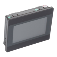
The HMI5000L Series is a line of graphic industrial operator interface terminals designed for various industrial applications. These touchscreens are configured using the EasyBuilder Pro Software, which provides the necessary tools for programming and setting up the HMI. The series includes a range of models, such as HMI5043L, HMI5070LB, HMI5102L, HMI5043LB, HMI5070DL, HMI5103L, HMI5043DL, HMI5070NL, HMI5120XL, HMI5070L, HMI5097DXL, HMI5121XL, HMI5097NXL, HMI5150XL, and HMI5100L.
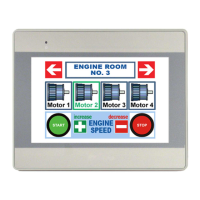
The primary function of these devices is to provide a user interface for industrial control systems, allowing operators to monitor and interact with machinery and processes. They are built to withstand harsh industrial environments, conforming to European CE requirements for noise emissions and immunity (EN55022 and EN55024 standards). The HMIs are rated for NEMA 4 (indoor) or IP65/IP66 installations, meaning their front enclosures protect against splashing water, wind-blown dust, rain, or hose-directed water when properly mounted.
For installation, careful attention to static awareness is crucial to prevent damage to the internal circuitry. Users are advised not to remove the rear cover, as this voids the warranty and exposes components to electrostatic discharge. Handling the HMI at a static-free, grounded workstation, discharging personal static, and connecting the chassis ground to a clean earth ground are recommended practices. The unit should be placed in an antistatic bag during transport.
Upon unpacking, users should verify the contents against the packing list, which typically includes the HMI5000L Series Touchscreen, a power connector, a mounting clamp kit, the HMI5000L Series Installation Guide, and for some models, a USB Stick Clamp and Spare Fuse Kit. Any shipping damage should be reported to the carrier immediately.
The HMI is designed to operate in temperatures ranging from 0° to 50°C (32° to 122°F) and is intended for indoor installations. It is important to avoid environments with severe mechanical vibration or shocks, rapid temperature variations, or high humidity, as these conditions can lead to condensation and damage. The HMI should not be operated in areas subject to explosions due to flammable gases, vapors, or dusts. It conforms to UL508 machine safety standards for use in Pollution Degree 2 Environments. If wiring is potentially exposed to lightning or power surges, appropriate surge suppression devices should be used.
Safety precautions include never connecting the HMI to an AC power source, as this will cause permanent damage. A hard-wired EMERGENCY STOP should be fitted in any system using an HMI to comply with ICS Safety Recommendations. It is also critical to use a DC power supply that meets the HMI's power requirements to prevent malfunction or damage. An internal fuse (except for 4.3” display models) is included to prevent damage from overcurrent conditions, though it is not guaranteed. DC voltage sources should provide proper isolation from AC power and similar hazards. The HMI should not be powered by a DC power supply used for inductive loads or for input circuitry to a programmable logic controller, as severe voltage spikes from these devices can cause damage.
Control panel design guidelines emphasize careful placement of system components and cable routing to enhance performance and integrity. Good grounding is paramount for safety and shielding. The control panel must be connected to a good, high-integrity earth ground. All earth ground wires from the HMI, PLC, power supply, and line filter should lead to a central earth ground point. The HMI chassis ground terminal should be connected to the control panel using a heavy-gauge, short braided cable (#14 AWG) or ground wire. If the control panel is non-conductive, the chassis ground terminal must connect to a clean earth ground point close to the panel. The power cable's shield wire should connect to the HMI's chassis ground terminal. The control panel should be connected to earth ground using a copper grounding rod. For hinged doors, a separate wire braid should be installed to ensure a long-term electrical connection.
Power supply selection is critical. The HMI requires an output of at least +24 VDC ±20% at its power connector, with HMI5043DL models specifically requiring +10.5~28VDC. A dedicated DC regulated power supply with adequate current rating is recommended. A power line filter at the AC input to the HMI power supply is highly recommended to safeguard against conducted RF noise. The wires connecting the filter to the power supply should be kept short, and the filter case should be connected to a quiet earth ground. The filter should have a current rating of at least 3 Amps with common mode and differential mode attenuation. For high-frequency noise, a resistor (~1 MΩ) and capacitor (~4700 pF) in parallel can be used to clean earth ground on the DC output. The power supply for the HMI should not be used to power switching relays, solenoids, or other active devices.
Connecting the HMI to power involves using the supplied 3-position connector. The power cable should be 18AWG, 2-conductor wire with a shield drain wire and protective shield. The red wire connects to the positive (+) input of the HMI power connector and the VDC positive (+) output of the power supply. The black wire connects to the negative (-) input of the HMI power connector and the VDC negative (-) output of the power supply. The power cable shield wire connects to the HMI power connector FG or ground input, with the other side connected to chassis ground. It is important to wait ten seconds after removing power before reapplying it to prevent damage.
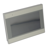
Panel preparation for mounting requires a metal panel or mounting surface that does not flex more than 0.010” to ensure a NEMA 4 seal. Sufficient clearance around the unit for hardware and cable connections is necessary. The panel area where the gasket contacts must be flat, free of scratches, and smooth. A sealant like silicone may be needed if the surface is not uniform. The panel cutout should be cleaned and deburred before installation. Mounting involves inserting screws into the clamps, positioning the HMI in the cutout, holding it in place, and tightening the screw clamps evenly to a recommended torque of 3.5 in/lbs. Overtightening can warp the overlay or damage the housing.
Configuration wiring for the HMI uses either an Ethernet Configuration Cable (P/N 7431-0104) or a USB Configuration Cable (P/N 7431-0115) with the EasyBuilder Pro software. A USB driver, included with the software, must be installed for USB connections. When connecting two powered devices via USB, a difference in ground potential can exist, potentially causing a damaging ground loop. The Maple Systems USB Configuration Cable (P/N 7431-0115) is recommended as its shield is not connected between the ends, preventing ground loops.
For Ethernet configuration, if using a switch or router, a straight-through or crossover cable may be required. The HMI needs a unique IP address on the same subnet as the development PC. This is set in the System Settings menu under the Network tab. Models like HMI5043DL, HMI5070DL, and HMI5097DXL have separate tabs for LAN1 and LAN2, which must be on different subnets for simultaneous operation. HMI5103L models also feature a Wireless tab for Wi-Fi connectivity, supporting IEEE 802.11 b/g/n with WPA-PSK/WPA2-PSK encryption. Wi-Fi is off by default and can be configured in the System Settings menu. When using Wi-Fi simultaneously with wired Ethernet, ensure connections are on different subnets.
Maintenance features include DIP switches or an 8-pin header for jumpers on some HMIs. These allow for different modes: Touchscreen Calibration, Hide System Toolbar, Boot Loader mode, and Normal operation. Touchscreen Calibration mode allows for calibrating the touchscreen and can also be entered by pressing the screen for several seconds during HMI power-up. The Hide System Toolbar option hides the arrow that accesses the System Settings menu. Boot Loader mode is for replacing or reinstalling the operating system and is intended for qualified repair personnel only, as improper use can damage the HMI. HMI Power must be cycled to enable the selected DIP switch or jumper mode.
EasyAccess 2.0 is pre-installed on HMI5043DL, HMI5070DL, HMI5097DXL, and HMI5103L models, enabling remote monitoring without an activation card. Fusing requirements note that if the display does not power on within two seconds, the internal fuse (except for 4.3" models) may have prevented damage from incorrect DC power polarity, requiring wiring to be checked. A USB Stick Clamp, included with some models, prevents a USB stick from disconnecting due to vibration. The USB Host port is designed for data storage only; USB hard drives should be powered by their own supply, and no devices should be charged from the USB port.
| Resolution | 800 x 480 pixels |
|---|---|
| Display Type | TFT LCD |
| Processor | 400 MHz RISC |
| Power Input | 24 VDC |
| Display Size | 7 inches |
| Touch Panel | Resistive |
| Memory | 128 MB Flash |
| Communication Ports | RS-232, RS-485 |
| USB Ports | USB Host |
| Operating Temperature | 0°C to 50°C |
| Storage Temperature | -20°C to 60°C |
| Enclosure | IP65 (Front Panel) |