Do you have a question about the Maquet SERVO-s and is the answer not in the manual?
General notes on the SERVO-s Ventilator System documentation and usage guidelines.
Explanation of symbols used in the manual and critical hazard warnings for safe operation.
Procedures and responsibilities for installing, servicing, and maintaining the SERVO-s.
Guidelines for authorized personnel and MAQUET's responsibility for service and parts.
Information on the environmental impact and construction materials used in the SERVO-s.
Details on articles of consumption, noise level, packing materials, and power consumption.
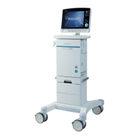
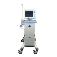
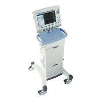
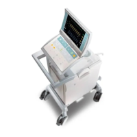
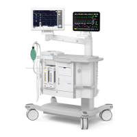
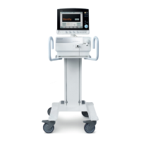
Introduction to the SERVO-s system, its main units, and software structure.
List of optional equipment that can be added to the SERVO-s Ventilator System.
Detailed description of the User Interface, its controls, display, and operational features.
Description of the PC 1777 Panel, its hardware versions, and associated features.
Identification of accessible parts, connectors, and modules on the Patient Unit.
Details on accessible internal components of the Patient Unit after cover removal.
Description of the expiratory cassette, its parts like flowmeter, and operational details.
Detailed explanation of the Breathing, Monitoring, Panel, and System ID software subsystems.
Introduction to system functions, memory types, and an overview of the chapter's content.
Detailed description of User Interface controls, PC 1777 Panel, loudspeaker, and touch screen features.
Explanation of TFT Display, backlight, touch screen, and key components of the inspiratory system.
Description of gas inlet, filters, transducers, nozzle units, solenoids, and inspiratory piping.
Details on the O2 cell, safety valve operation, inspiratory outlet, and PC 1861 pneumatic back-plane.
Description of the expiratory section, cassette, heating foil, ultrasonic flowmeter, and expiratory inlet.
Details on expiratory valve, PC 1786/1785, PC 1860, and pressure transducers.
Description of PC 1784 Expiratory channel, PC 1771 Control, and PC 1772 Monitoring boards.
Explanation of power supply components, mains inlet, AC/DC converter, and PC 1862 connectors.
Description of PC 1863 Power control, battery modules, internal fan, and the control cable.
General procedures, preparations, handling of PC boards, and assembly guidelines for the SERVO-s.
Details on tightening torques and threadlocking adhesives required during assembly.
Step-by-step instructions for separating the User Interface front panel and accessing internal parts.
Instructions for removing the PC 1777 Panel and notes on system SW re-installation.
Procedure for replacing PC 1777 Type 1 with a kit, including disassembly and assembly steps.
Steps for disconnecting cables and removing the PC board Backlight Inverter for Type 1 and Type 2.
Instructions for removing the TFT Display and configuring DIP switches on PC 1777 Type 2.
Steps to access and replace backlight lamps for TFT Display Type 1 and Type 2.
Instructions for removing the touch screen assembly and applying label strips to the front panel.
Procedure for releasing screws and removing the main and side covers of the Patient Unit.
Steps for disconnecting the control cable and removing the User Interface and gas modules.
Instructions for removing battery modules, PC 1771/1772 boards, and the AC/DC converter.
Steps for removing PC 1863 Power control, PC 1862 connectors, and PC 1860 Main back-plane.
Procedures for removing the internal fan, inspiratory channel, and safety valve membrane.
Instructions for removing the PC 1861 Pneumatic back-plane and PC 1784 Expiratory channel.
Steps for removing the PC 1785 Expiratory channel connector and the expiratory valve coil.
Detailed procedure for removing and mounting the expiratory cassette valve membrane.
Guidance on carefully connecting control cable connectors and managing the cable.
Procedures for servicing and replacing battery modules, including status checks.
Explanation of battery status indicators, usable backup time, and charge levels.
Steps for replacing lithium batteries on PC 1771 and PC 1772, including ESD precautions.
Guide to using the Menu and Biomed functions for service, event logs, and reporting.
Details on editing configuration, setting date/clock, changing access codes, and O2 cell adaptation.
Information on SW updates, upgrades, installation procedures, and using the Field Service System.
General troubleshooting guidance and an introduction to technical error codes.
Steps to eliminate operational errors and information on system SW version for troubleshooting.
Performing the pre-use check and recommended actions if tests fail, including FSS usage.
Detailed procedures and failure recommendations for internal, barometer, and gas supply pressure tests.
Checks for internal leakage, test tube connection, and expiratory cassette seating.
Recommended actions for internal leakage test failures and system volume errors.
Calibration and checks for pressure transducers and expiratory valve coil, with failure recommendations.
Procedures for checking safety valve opening pressure and O2 cell calibration.
Tests for flow transducer calibration and battery switch functionality.
Tests for patient circuit leakage, alarm states, and external alarm system functionality.
Recommended actions for technical error codes related to monitoring and power supply failures.
Recommended actions for errors related to valves, node communication, and flowmeter issues.
Recommended actions for panel, battery, and communication timeout error codes.
Recommended actions for barometer, clock, checksum, power, and shutdown error codes.
Recommended actions for breathing, panel device, backlight, and button stuck error codes.
Recommended actions for communication errors, expiratory flow meter, and cassette faults.
General information, preparations, and equipment required for preventive maintenance.
Details on the 5,000-hour maintenance kit and procedures for performing preventive maintenance.
Procedure for replacing filters and nozzle units in the gas modules.
Steps for replacing the inspiratory pressure transducer filter and O2 cell bacteria filter.
Maintenance procedures for internal fan filter, internal fan, and expiratory cassette.
Checks for User Interface, barometric pressure, gas supply, batteries, safety inspection, and completing maintenance.
Alphabetical listing of all topics covered in the manual with corresponding page numbers.
Introduction to the diagrams section, including standard connectors and functional main blocks.
Detailed pin assignments and descriptions for control, supply input, and alarm output connectors.
Visual representation of the SERVO-s system architecture, components, and signal flow.
| Device Type | Mechanical Ventilator |
|---|---|
| Model | SERVO-s |
| Patient Range | Adult, Pediatric |
| Display | Color Touchscreen |
| Power Supply | 100-240 V AC, 50/60 Hz |
| FiO2 Range | 21-100% |
| Manufacturer | Maquet (now Getinge) |
| Ventilation Modes | Volume Control, Pressure Control, Pressure Support, SIMV, CPAP |
| Monitoring Parameters | Pressure, Volume, Flow, Oxygen Concentration (FiO2), Respiratory Rate, Minute Volume, I:E Ratio |
| Respiratory Rate | 1 to 150 breaths per minute |
| PEEP/CPAP | 0 to 35 cmH2O |
| Trigger Sensitivity | Flow or Pressure Trigger |
| Alarms | High/Low Pressure, High/Low Volume, Apnea, High/Low FiO2 |
| Connectivity | Ethernet |
| Battery Backup | Yes (Internal Battery) |