Do you have a question about the Marantz 500 and is the answer not in the manual?
Updates regarding transistor replacements and beta range charts.
Information on new, improved power output transistors and replacement procedures.
Overview of the manual, intended audience, and critical safety warnings.
Detailed performance parameters like power output, distortion, frequency response, and dimensions.
High-level overview of the amplifier's circuit blocks and signal flow.
Lists essential test equipment and their specific models or types for servicing.
Diagrams for AC power control and amplifier output load boxes used in testing.
Procedures to verify the amplifier's operational performance after repairs.
Steps to take before starting performance verification tests.
Verifies bias, relay operation, DC balance, hum/noise, power, distortion, frequency response, and gain.
Detailed procedures for internal adjustments like bias and DC balance.
Covers gain differential, channel separation, and meter calibration tests.
Includes disassembly, preliminary steps, and bias test setup.
Adjusts the Safe Operating Area limits.
Oscilloscope connection diagram and expected display for SOA adjustment.
Steps for calibrating the front panel meters.
General notes on disassembly, re-assembly, and conversions.
Procedures for removing top/bottom covers and the front panel assembly.
Procedures for removing the driver board and rear panel assemblies.
Steps to remove the Channel A heatsink component assembly.
Guidance on replacing heatsink-mounted transistors, including thermal compound.
Steps to remove the Channel A power amplifier board.
Steps to remove Channel B heatsink and power amplifier assemblies.
Steps to remove the rectifier/relay board.
Instructions for converting the unit for different line voltages (100/220 VAC).
Introduction to the component parts list section.
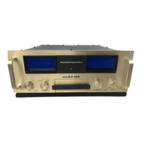
Visual layout of the front panel assembly and its parts list.
Visual layout of the power supply assembly and its parts list.
Component layout diagram for the driver board assembly.
Detailed list of components for the power amplifier board.
Component layout diagram for the power amplifier board.
Visual layout of the meter board assembly and its parts list.
Component layout diagram for the rectifier/relay board.
Comprehensive schematic diagrams of the amplifier's circuitry.
Charts detailing transistor types, beta ranges, color codes, and dash numbers.
Log of service notes and remarks with dates.