EasyManua.ls Logo

Marantz 5030 User Manual

Marantz 5030
52 pages
To Next Page IconTo Next Page
Page #1 background imageLoading...
Page #1 background image

Table of Contents

Question and Answer IconNeed help?

Do you have a question about the Marantz 5030 and is the answer not in the manual?

Marantz 5030 Specifications

General IconGeneral
BrandMarantz
Model5030
CategoryCassette Player
LanguageEnglish

Summary

INTRODUCTION

Printed Wiring Boards (P.W. BOARDS)

Lists the various Printed Wiring boards constituting the chassis of Model 5030.

Test Equipment for Servicing

Lists necessary instruments and materials for measuring or checking the Model 5030.

3. DISASSEMBLY

Removing Cassette Case Escutcheon

Instructions for removing the cassette case escutcheon.

Removing Main P.W. Board

Instructions for removing the main Printed Wiring board.

Removing Mechanical Chassis

Instructions for removing the mechanical chassis.

4. ADJUSTMENT PROCEDURES

Mechanical Adjustments

Details various mechanical adjustments for the cassette deck.

Play Timing and Torque Adjustments

Adjustments for play timing, torque, and reel clutch.

Motor Pulley, Tape Speed, and Idler Adjustments

Adjustments for motor pulley position, tape speed, and rewind idler pressure.

Switch Positioning Adjustments

Procedures for positioning various switches like motor, pause muting, and start muting.

Memory Rewind and Interlocking Mechanism Adjustments

Adjusting memory rewind switch and interlocking mechanism.

4.2 ELECTRICAL ADJUSTMENTS AND MEASUREMENTS

Precautions Before Adjustment and Measurement

Important precautions to follow before performing adjustments and measurements.

Definitions

Defines key terms like "normal playback state" and "normal recording state".

Head Azimuth and Tape Speed Adjustments

Head Azimuth Setup, Procedures, and Cautions

Setup, step-by-step procedures, and cautions for head azimuth adjustment.

Tape Speed Setup, Procedures, and Cautions

Setup, step-by-step procedures, and cautions for tape speed adjustment.

Playback Equalizer and Output Adjustments

Playback Equalizer Setup and Procedures

Setup and step-by-step procedures for playback equalizer adjustment.

Playback Output Setup, Procedures, and Caution

Setup, procedures, and caution for playback output adjustment.

VU Meter and Recording Bias Current Adjustments

VU Meter Setup and Procedures

Setup and step-by-step procedures for VU meter adjustment.

Recording Bias Current Setup and Procedures

Setup and step-by-step procedures for recording bias current adjustment.

Recording Current and Frequency Response Adjustments

Recording Current Setup and Procedures

Setup and step-by-step procedures for recording current adjustment.

Record-Playback Frequency Response Setup and Procedures

Setup and step-by-step procedures for record-playback frequency response adjustment.

Record Playback Output and Dolby Circuit Adjustments

Record Playback Output Setup, Procedures, and Caution

Setup, procedures, and caution for record playback output level adjustment.

Dolby Circuit Encoder/Decoder Adjustments and Caution

Adjustment procedures for Dolby circuits with caution.

Tape Speed and Wow/Flutter Measurements

Tape Speed Setup, Procedures, and Caution

Setup, procedures, and caution for tape speed measurement.

Wow/Flutter Setup, Procedures, and Caution

Setup, procedures, and caution for wow and flutter measurement.

Playback Level and Signal-to-Noise Ratio Measurements

Playback Output Level Setup and Procedures

Setup and step-by-step procedures for playback output level measurement.

Playback S/N Ratio Setup, Procedures, and Cautions

Setup, procedures, and cautions for playback signal-to-noise ratio measurement.

Playback and Record-Playback Frequency Response Measurements

Playback Frequency Response Setup and Caution

Setup, procedures, and caution for playback frequency response measurement.

Record-Playback Output Level Setup and Procedures

Setup and step-by-step procedures for record-playback output level measurement.

Harmonic Distortion and S/N Ratio Measurements

Harmonic Distortion Setup, Procedures, and Cautions

Setup, procedures, and cautions for record-playback harmonic distortion measurement.

S/N Ratio Setup, Procedures, and Caution

Setup, procedures, and caution for record-playback signal-to-noise ratio measurement.

19. Record-Playback Frequency Response Measurement

Setup and Procedures

Setup and step-by-step procedures for record-playback frequency response measurement.

Erasing Effect and Leak Bias Measurements

Erasing Effect Setup, Procedures, and Standard

Setup, procedures, and standard for erasing effect measurement.

Leak Bias Setup, Procedures, and Standard

Setup, procedures, and standard for leak bias measurement.

Cross Talk and Channel Separation Measurements

Cross Talk Setup, Procedures, and Standard

Setup, procedures, and standard for cross talk measurement.

Channel Separation Setup, Procedures, and Standard

Setup, procedures, and standard for channel separation measurement.

5. VOLTAGE CONVERSION FOR EUROPEAN MODEL

Voltage Conversion Caution

Critical safety caution before voltage conversion.

6. DIAGRAMS

Level Diagram

Illustrates signal levels for playback and recording operations.

6.3 CONNECTION DIAGRAM

6.2 BLOCK DIAGRAM

6.4 SCHEMATIC DIAGRAM

6.5 PRE-AMP, POWER SUPPLY, DOLBY BOARD SCHEMATIC DIAGRAM AND COMPONENT LOCATIONS - P100

Circuit Board Schematics and Locations

LED, Terminals, and Fuse Board Schematics

Schematics and component locations for LED, Terminals, and Fuse boards.

Volume/Peak, Monitor Board Schematics

Schematics and component locations for Volume/Peak and Monitor boards.

6.11 POWER SUPPLY, BIAS OSCILLATOR BOARD SCHEMATIC DIAGRAM AND COMPONENT LOCATIONS - P900

6.12 MEMORY BOARD SCHEMATIC DIAGRAM AND COMPONENT LOCATIONS - P800

7. MAJOR COMPONENT LOCATIONS

Cabinet - Front View Component Locations

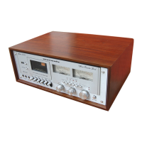
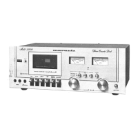
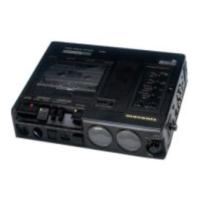
Identifies major components located on the front view of the cabinet.

Chassis - Top View Component Locations

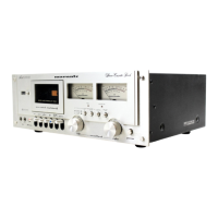
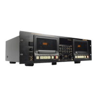
Identifies major components located on the top view of the chassis.

7.3 CABINET - REAR VIEW

8. EXPLODED VIEWS AND PARTS LIST

Top Cover and Main Chassis Parts

Exploded view and parts list for the top cover and main chassis.

8.2 [P02-99] FRONT PANEL AND CHASSIS

8.3 [P03-99] ASSOCIATED MECHANISM FOR CASSETTE TAPE OPERATION

8.4 [P04-99] REAR PANEL

8.5 [P05-00] BUTTONS FOR TAPE MECHANISM OPERATION

8.6 [P06-99] HEAD CHASSIS

8.7 [P07-99] FLYWHEEL

8.8 [P08-99] SWITCH LOCATION FOR THE TAPE MECHANISM OPERATION

8.9 [P09-99] PARTS ASSEMBLED ON THE TOP CHASSIS

8.10 [P10-99] PARTS ASSEMBLED ON THE REVERSE CHASSIS

8.11 [M01-99] P.W. BOARDS AND GENERAL PARTS

9. GENERAL SPECIFICATIONS

Physical and System Specifications

Details on style, tape system, tracking, speed, heads, motor, and systems.

Frequency Response and Noise

Specifications for frequency response and signal-to-noise ratio.

Output and Input Specifications

Details on line output, input sensitivity, and headphone output.

Performance Metrics

Wow/flutter, rewind, fast forward times, and AC voltage.

Power, Dimensions, and Weight

Information on power consumption, dimensions, and weight.

Related product manuals