Do you have a question about the Marantz 74 CD-52/25B and is the answer not in the manual?
General electrical and physical specifications for the CD player.
Details of the RC-5 remote control interface.
Specifications for the audio line output.
Specifications for the headphone output.
Physical dimensions and weight of the player.
Specifications related to the laser diode.
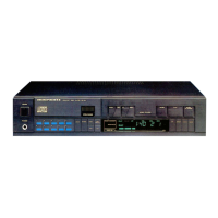
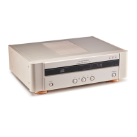
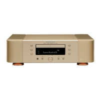
Identification and function of front panel controls.
Identification and function of back panel connections.
Step-by-step guide for powering on the device.
Detailed checks and adjustments for common faults.
List and explanation of system and operating error codes.
General advice, handling, ESD, and mounting/dismounting.
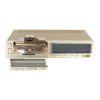
Guidance on disassembling cabinet and loading mechanisms.
Illustrated list of mechanical components and their identification.
High-level diagram of the CD player's functional blocks.
Schematic for the device's power supply.
Schematic for the front panel display and controls.
Schematic for the servo control system.
Schematic for the audio decoding functions.
Schematic for the Digital-to-Analog Converter section.
Schematic for the headphone amplifier circuit.
Diagram showing internal component connections.
Component placement diagram for servo and decoder boards.
List of components for the servo and decoder boards.
List of components for the headphone panel.
List of components for the control and display panels.
| DAC | 1-bit Delta-Sigma |
|---|---|
| Transport | CDM-4/19 |
| Frequency Response | 2Hz - 20kHz |
| Dynamic Range | 96dB |
| Channel Separation | 100dB |
| Total Harmonic Distortion | 0.002% |
| Dimensions | 430 x 100 x 310 mm |
| Weight | 4.5 kg |
| Type | CD Player |
| Line Output | 2V RMS |
| Digital Outputs | Coaxial |
| Output Voltage | 2V RMS |