Do you have a question about the Marantz 74CD50 01B and is the answer not in the manual?
Ensures set restoration to original condition using specified parts.
Details required information for ordering parts by mail or telex.
Lists national subsidiaries and agents for parts procurement.
Explains the system of chapter, sequence, and supplementary/replacement page numbering.
Illustrates general, dismounting, mounting techniques, and soldering precautions.
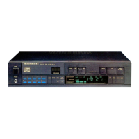
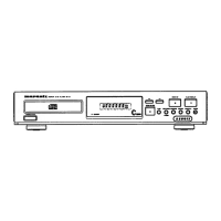
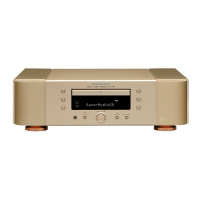
Details the buttons and indicators on the front of the CD player.
Explains functions operated exclusively via the remote handset.
Describes analog and digital output connections and remote control interface.
Instructions for removing transit clamps before player operation.
Lists key technical parameters of the compact disc player.
Details ESD sensitivity and handling precautions for repairs.
Instructions for creating a disc hold-down for service measurements.
Lists essential service tools and guides for using the faultfinding tree.
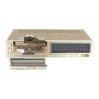
Step-by-step guide for disassembling the player's cabinet.
Instructions for removing the control and display panel assembly.
Lists part numbers and descriptions for mechanical components.
Diagram showing the arrangement of various player components and their numbers.
Details microprocessor signals and their modes for diagnostics.
Procedures and voltage checks for the laser supply circuit.
Procedures for adjusting laser current and focus offset.
Tests and adjustments for high-speed disc rotation and track following.
Signal checks for track jumping and audio output issues.
Lists system errors, their causes, and checks for troubleshooting.
Details the DEEM circuit and specification measurements.
Covers DOBM digital output and a list of operating error codes.
Illustrates the overall wiring connections of the player.
Details power supply circuits and voltage adapter configurations.
Shows the functional blocks of the servo and decoding circuitry.
Defines common abbreviations used in the manual.
Detailed circuit diagram for the servo control system.
Circuit diagram for the servo and decoder panel components.
Continued circuit diagram for the servo and decoder panel.
Circuit diagram for the first part of the decoding system.
Circuit diagram for the second part of the decoding system.
Schematic for the player's control and display interface board.
Circuit diagram for the variable line output stage.
Diagram illustrating wiring between major player sections.
List of electrical components for the servo and decoder sections.
Catalog of resistors and capacitors with part numbers and values.
List of electrical components for the control and display panel.
Catalog of semiconductor devices and connectors with part numbers.
Explanation of standard symbols used in circuit diagrams.