16
16
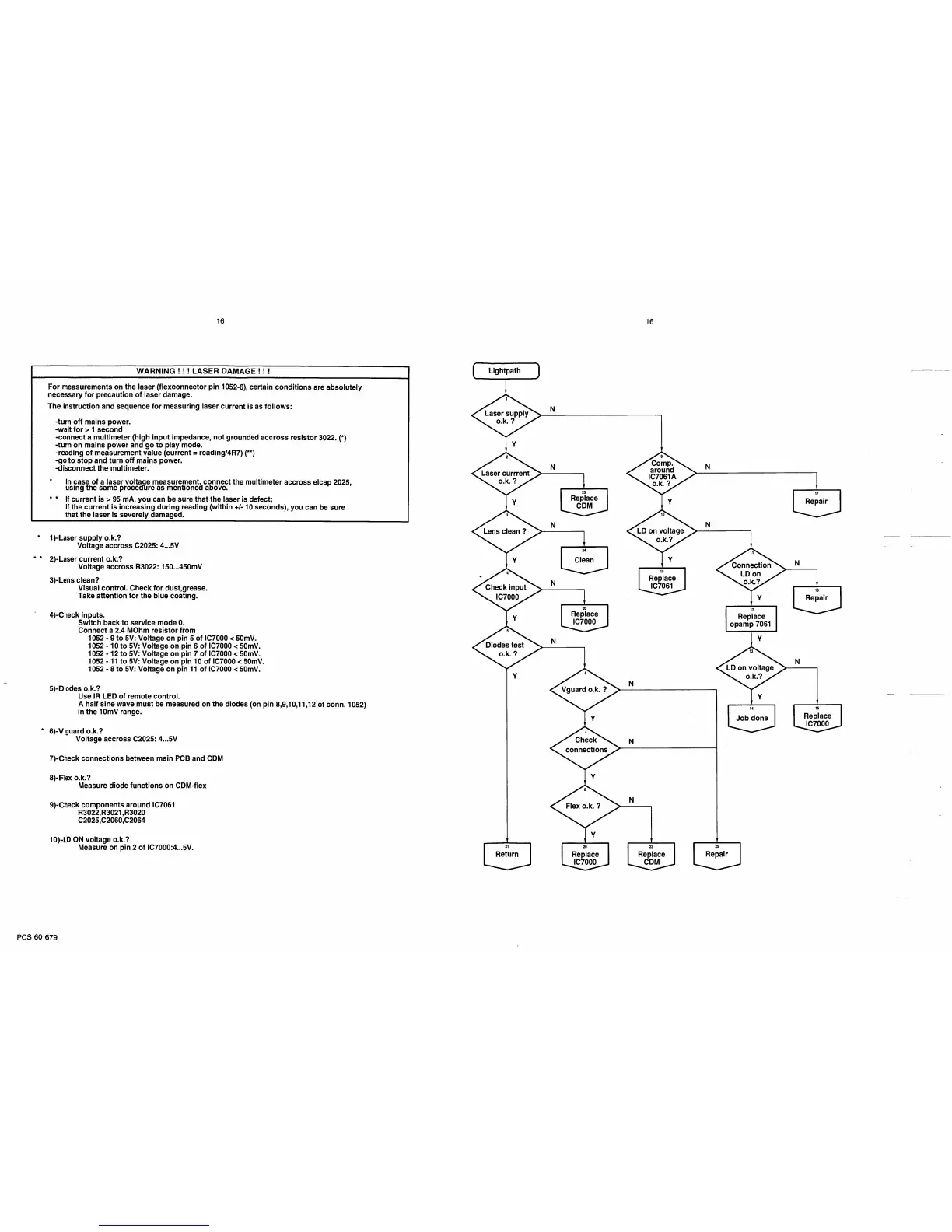
WARNING ! ! ! LASER
DAMAGE
! ! !
For
measurements
on the
laser
(flexconnector pin
1052-6),
certain
conditions
are
absoiutely
necessary
for
precaution
of iaser
damage.
The
instruction and sequence for measuring
iaser
current is as foliows:
-turn off mains power.
-wait for >
1 second
-connect a muitimeter (high input impedance,
not
grounded accross
resistor
3022.
(*)
-turn
on
mains power and
go
to piay
mode.
-reading
of measurement value
(current
=
reading/4R7)
(**)
-go to stop and turn
off
mains
power.
-disconnect the multimeter.
*
in
case of a laser
voltage measurement, connect
the
multimeter
accross
elcap
2025,
using the
same
procedure
as
mentioned
above.
*
*
If current
is >
95 mA,
you
can
be
sure that the
laser
is
defect;
If
the current
is increasing
during
reading
(within
+/-
10
seconds),
you can
be sure
that the laser is
severely
damaged.
*
1)-Laser supply
o.k.?
Voltage
accross
C2025: 4...5V
*
*
2)-Laser current o.k.?
Voltage accross R3022: 150...450mV
3)
-Lens clean?
Visual
control. Check
for dust,grease.
Take
attention for
the blue coating.
4)
-Check inputs.
Switch back to service
mode 0.
Connect a
2.4
MOhm
resistor from
1052
-
9
to
5V:
Voltage
on pin 5 of
IC7000 <
50mV.
1052
-
10
to
5V:
Voltage
on pin 6 of IC7000 < 50mV.
1052
-
12 to 5V: Voltage on pin 7 of IC7000
< 50mV.
1052
-
11 to 5V: Voltage on pin
10
of
IC7000 <
50mV.
1052-8
to
5V:
Voltage on
pin
11 of IC7000 <
50mV.
5)-Diodes o.k.?
Use IR LED
of remote
control.
A half sine wave
must
be
measured on
the
diodes
(on pin
8,9,10,11,12
of conn.
1052)
in
the
lOmV
range.
*
6)-V
guard o.k.?
Voltage accross C2025: 4...5V
7)-Check
connections between main
PCB
and
CDM
8)-Flex
o.k.?
Measure diode functions on
CDM-flex
9)-Check
components
around IC7061
R3022,R3021,R3020
C2025,C2060,C2064
10)-LD
ON voltage o.k.?
Measure on
pin
2 of IC7000:4...5V.
PCS
60
679
 Loading...