NEXT
Button pressed?
Y
N
SHUFFLE
Button pressed?
Y
PROGRAM
Button pressed?
Y
N N
PLAY
Button pressed?
Y
N
NEXT
Button pressed?
Y
PLAY
Button pressed?
N
STOP
Button pressed?
Y
Y
N
PREV
Button pressed?
Y
Display shows
CD
Disc Motor turns CCW
Display shows
CCW
Disc Motor turns CW
Display shows
CW
Slide moves outside
Slide moves inside
Display shows
FOC OK
Display shows
FOC ERR
FOCUS found?
Y
Y
N
STOP
Button pressed?
Y
N
Display shows
FOC XXX
Disc Motor Slide Motor
Focus Servo Test
Motor Test
PLAY
Button pressed?
STOP
Button pressed?
NN
Disc speeds up
Display shows
DISC
Disc Servo Test
PLAY
Button pressed?
Y
Y
STOP
Button pressed?
Y
NN
Display shows
RDL
Radial Servo Test
FOC ERR = Focus not found
FOC OK = Focus found
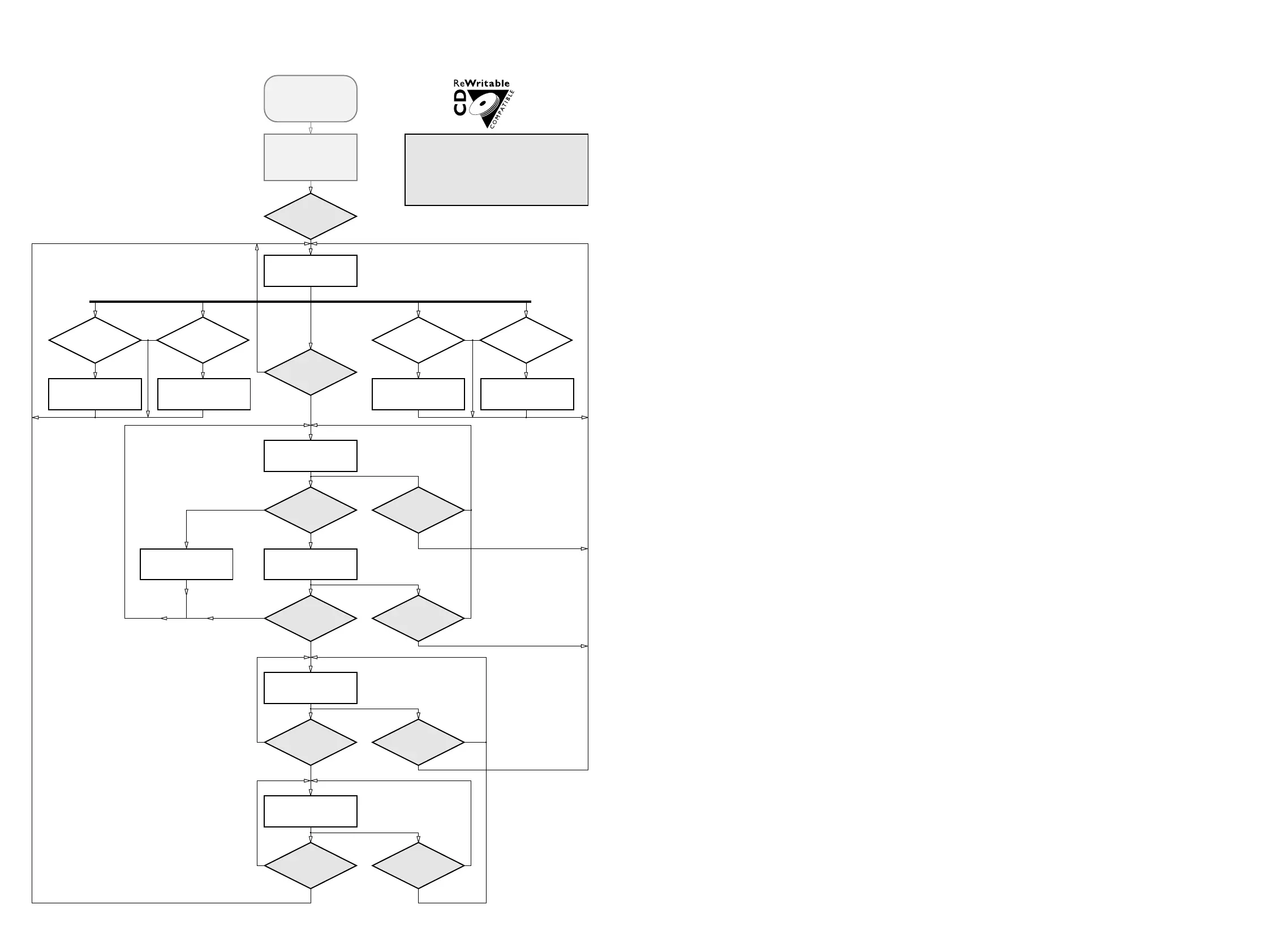
To start service test
program hold
PLAY & PAUSE depressed
while plugging in
the mains cord
Display shows number of
ROM version
"S Vzz"
In case of focus lost FOC ERR
will be displayed and
Focus Servo Test is entered again
It is possible to control the
slide motor with the
NEXT & PREV button
SERVICE TEST PROGRAM CD-Part
STP-CD Part CD713/CD723 (980429)
Since the CD-RW reflects much less light than an ordinary
CD-A, the gain of the HF-amplifier stage and the sensitivity
of the ADC inside the signal processor must be increased.
The gain is switched via the HG line (pin41 of CD7), the
ADC-sensitivity is switched via software (µP → CD7).
During start-up the correct mode is choosen automatically;
in the service test program it can be switched manually in
order to allow individual measurements in both conditions.
Sensitivity can be toggled
via EDIT Button.
CD RW resp. CD NORM is displayed
for two seconds.
STOP
button pressed in any step returns
to begin of Service Testprogram.
NOTE: If sensitivity is switched to high
the set will not work with normal Audio CDs!
SAA7372 – DECODER AND DIGITAL SERVO IC CD7
Pin Name Direction Description
–––––––––––––––––––––––––––––––––––––––––––––––––––––––––––––––––––––––––––––––––––––––––––––––––––––––––––
1 VSSA1 GND supply (analog) of CD7
2 VDDA1 +4V supply (analog) of CD7
3 D1 HF-preamp → CD7 unipolar current input (central diode signal input)
4 D2 HF-preamp → CD7 unipolar current input (central diode signal input)
5 D3 HF-preamp → CD7 unipolar current input (central diode signal input)
6 VRL GND reference input for ADC
7 D4 HF-preamp → CD7 unipolar current input (central diode signal input)
8 R1 HF-preamp → CD7 unipolar current input (satellite diode signal input)
9 R2 HF-preamp → CD7 unipolar current input (satellite diode signal input)
10 IREFT → CD7 current reference for calibration ADC
11 VRH not connected reference output from ADC
12 VSSA2 GND supply (analog) of CD7
13 SELPLL +4V selects whether internal clock multiplier PLL is used
14 ISLICE CD7 → current feedback from data slicer
15 HFIN → CD7 comparator signal input
16 VSSA3 GND supply (analog) of CD7
17 HFREF → CD7 comparator common mode input
18 IREF → CD7 reference current pin (nom. VDD/2)
19 VDDA2 +4V supply (analog) of CD7
20 TEST1 GND test control input
21 CRIN X-Tal → CD7 crystal/resonator input
22 CDOUT X-Tal → CD7 crystal/resonator output
23 TEST2 GND test control input
24 CL16 not connected 16.9344MHz system clock output
25 CL11 not connected 11.2896MHz or 5.6448MHz clock output (3-state)
26 RA CD7 → servo driver radial actuator output
27 FO CD7 → servo driver focus actuator output
28 SL CD7 → servo driver slide actuator output
29 TEST3 GND test control input
30 VDD1P +4V supply (digital) of CD7
31 DOBM CD7 → digital output bi-phase mark output (3-state)
32 VSS1 GND supply (digital) of CD7
33 MOTO1 CD7 → servo driver motor output1 of CD7; versatile (3-state)
34 MOTO2 CD7 → servo driver motor output2 of CD7; versatile (3-state)
35 SBSY not connected subcode block sync (3-state)
36 SFSY not connected subcode frame sync (3-state)
37 RCK GND subcode clock input
38 SUB not connected P to W subcode bits (3-state)
39 VSS2 GND supply (digital) of CD7
40 V5 not connected versatile output pin of CD7
41 V4 not connected versatile output pin of CD7
42 V3 not connected versatile output pin of CD7 (open drain)
43 KILL CD7 → kill output; programmable (open drain)
44 MISC not connected C2 error flag; output only defined in CD-ROM modes (3-state)
45 DATA CD7 → DAC serial data output (3-state)
46 WCLK CD7 → DAC word clock output (3-state)
47 VDD2P +4V supply (digital) of CD7
48 BCLK CD7 → DAC serial bit clock output (3-state)
49 VSS3 GND supply (digital) of CD7
50 CL4 not connected 4.2336MHz µP clock output
51 SDA µP → CD7 µP interface data I/O line (open drain output)
52 SCL µP → CD7 µP interface clock line
53 RAB µP → CD7 µP interface R/W and load control line
54 SILD µP → CD7 µP interface R/W and load control line
55 NC no connection
56 VSS4 GND supply (digital) of CD7
57 RESET µP → CD7 power-on reset input (active low)
58 STATUS not connected servo interrupt request line/CD7 status register output (open drain)
59 VDD3C +4V supply core (digital)
60 C2FAIL not connected indication of correction failure (open drain)
61 CFLG not connected correction flag output (open drain)
62 V1 → CD7 versatile input pin
63 V2 → CD7 versatile input pin
64 LDON CD7 → 7820 laser drive on output (open drain)
Abbreviations CD Part
 Loading...