Press Open/Close
Tray opened ?
N
Y
Load disc
press play
TOC on display ?
N
Y
Check: Supply voltages +A, +5V
Communication lines to P of apparatus.
Motordriver 7855, Safety resistor 3849.
Tray mechanism, wiring, tray switch
Slide motor ok ?
N
Y
Enter Step 1
Focus Search
Laser light ?
N
Y
Load disc
Focus ok ?
N
Y
Enter Step 2
Disc Test
Disc turns ?
N
Y
Enter Step 3
Radial servo
Radial Servo ok ?
N
Y
Enter Service Test Program
"CD Servo Test"
remove disc
Leave Service Test Program
press play
Check: Signal processor (7860) Pin 64
TS 7822
CD Mechanism
Check: Wiring of CD Mechanism
Power supply of Signal processor (7860)
Reference voltage R3850 - GND
OPAMP 7852
Check: Eye Pattern on MP1
Signal Processor 7860 Pin 32,33
Motordriver 7852
CD Mechanism
Check: Signal processor (7860) Pin 27
Power supply 7851
Motordriver 7851
CD Mechanism
Check: Signal processor (7860) Pin 26
Motordriver 7851
CD Mechanism
A
A
Audio signal ?
N
only one channel ?
N
Y
Y
Check: DAC (not part of the ECO Shortloader) Check: Communication lines of signal processor 7860 -DAC
Connector 1802
DAC (not part of the ECO Shortloader)
Digital out ?
(optional)
N
Y
Connector 1880
Signal Processor 7860 - pin 31
Intermit. failurs ?
N
Y
Set OK
Check:
Enter Service Testprogram
"CD PLAY TEST"
See error table
Enter Service Testprogram
"CD PLAY TEST"
See error table
TOC on display ?
N
Y
BEGIN
END
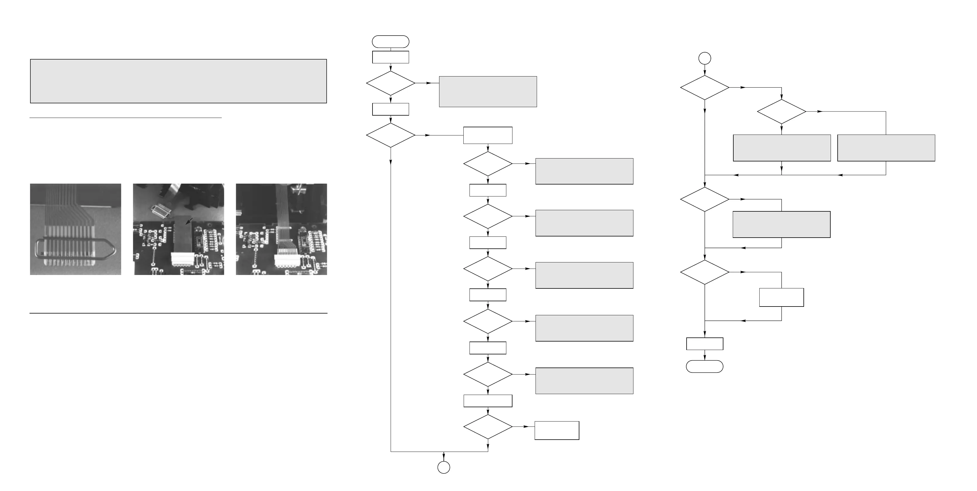
Faultfinding tree CDSL Mk3(IIs), 060698
Remarks
The following steps have to be done when replacing the CDM mechanism:
1. Disconnect old CD drive flexfoil from printed board
2. Connect paperclip to CD drive flexfoil to short-circuit flexfoil (fig.1)
3. Short-circuit printed board with
brass-sheet (4822 321 11197) plugged into the flexfoil connector (fig.2)
4. Remove old CD drive
5. Position new CD drive in its studs
6. Remove short-circuit from printed board connector
7. Remove short-circuit from flexfoil of new CD drive
8. Connect new flexfoil to print connector (fig.3)
fig.1 fig.2 fig.3
CHARGED CAPACITORS ON THE CD BOARD MAY DAMAGE THE CD-ELECTRONICS WHEN
CONNECTING A NEW CD DRIVE. THAT´S WHY, BESIDES THE SAFETY MEASURES LIKE
• SWITCH OFF POWER SUPPLY
• ESD PROTECTION
ADDITIONAL ACTIONS MUST BE TAKEN BY THE REPAIR TECHNICIAN.
WARNING
4822 321 11197