15
PM3392A
CH1!10.0 V= MTB1.00ms ch1+
0V
+4V
-34V
PM3392A
CH1!2.00 V=
CH2 2 V= MTB10.0ms ch1+
+5V
0V
+5V
0V
I
2
C DATA
I
2
C CLK
PM3392A
CH1!10.0 V= MTB1.00ms ch1+
0V
+5V
-34V
Supply voltages
The display board receives several voltages via connector
JY01.
• VFTD : -34V ±5% measured at pin 2 of conn. JY52.
• VDC1-VDC2 : 4V1 ±10% measured between pin 1 and 3 of
conn. JY52.
• +5V : + 5V ±5% measured at pin 10 of conn. JY52.
Voltages VFTD, VDC1 and VDC2 are produced in the Switching
Power Supply Board and sent to the display board via the CDR
main board. The +5V voltage is produced on the CDR main
board as D5V.
Clock signal
As clock driver for the display controller, a resonator of 8 Mhz
(XY01) is used. The signal can be measured at pins 8 and 9 of
the display controller : 8 Mhz ±5%.
Control signals
RESETN
The reset signal comes via pin 4 of conn. JY52 from the DASP
master processor on the CDR main board (SYS_RESET). The
reset is low active. It should be kept low during power up for at
least 3 machine cycles with supply voltage in operating range
and a stable clock signal (1 machine cycle = 12 x 1/Fc (8 Mhz)
sec.). During normal operation, the reset should be high (3V3).
The high signal is 3V3 because the DASP operates on 3V3.
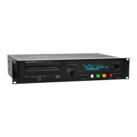
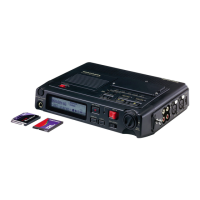
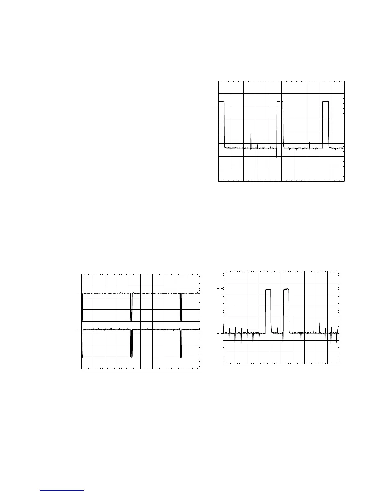
I2C DATA/I2C CLK
These lines connect to the DASP master processor via
respectively pin 5 and pin 7 of conn. JY52. When there is
no communication, they should have the high level (+5V). The
oscillogram below gives an indication of how these signals
should look like.
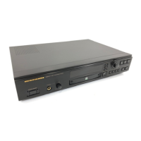
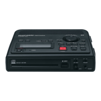
Grid lines
Level and timing of all grid lines, G1-->G15, can be checked
either at the FTD itself or at the display controller. Grid lines
G13, G14 and G15 each have an extra current amplifier in line
: QY04 for G13, QY03 for G14 and QY02 for G15. A typical
grid line signal shows in the oscillogram below.
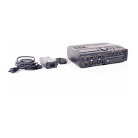
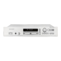
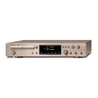
Segment lines
Level and timing of all segment lines, P-->P21, can be
checked either at the FTD itself or atthe display controller.
The data on these segment lines however, depends on the
characters displayed. The oscillogram below shows a
segment line with data. A segment line without data
maintains a -30V level.
FTD drive lines
Filament voltage
Should measure 4.3V ±10% (=VDC1-VDC2) between pins 1-2
and pins 52-53 of FTD(VY01).
7.1.2 Test instructions
Figure 7-2 “I2C SIGNALS”
Figure 7-3 “OSD”
Figure 7-4 “SEGMENT LINE”
 Loading...