16
PM3392A
CH1!2.00 V= MTB5.00ms ch1+
0V
+5V
CL 96532121_031.eps
141099
PM3392
Pin3
Pin1
CH1 5.00 V=
CH2 5.00 V= MTB20.0ms- 1.92dv ch2-
CL 96532121_032.eps
141099
PM3392
Pin3
Pin1
CH1 5.00 V=
CH2 5.00 V= M TB20.0ms- 1.92dv ch2-
CL 96532121_033.eps
141099
PM3392A
CH1!2.00 V= MTB20.0ms ch1+
1
+5V
0V
CL 96532121_034.eps
141099
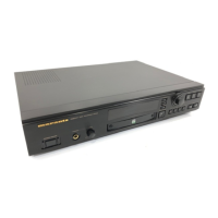
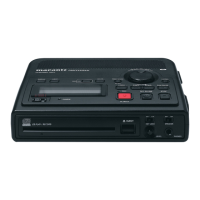
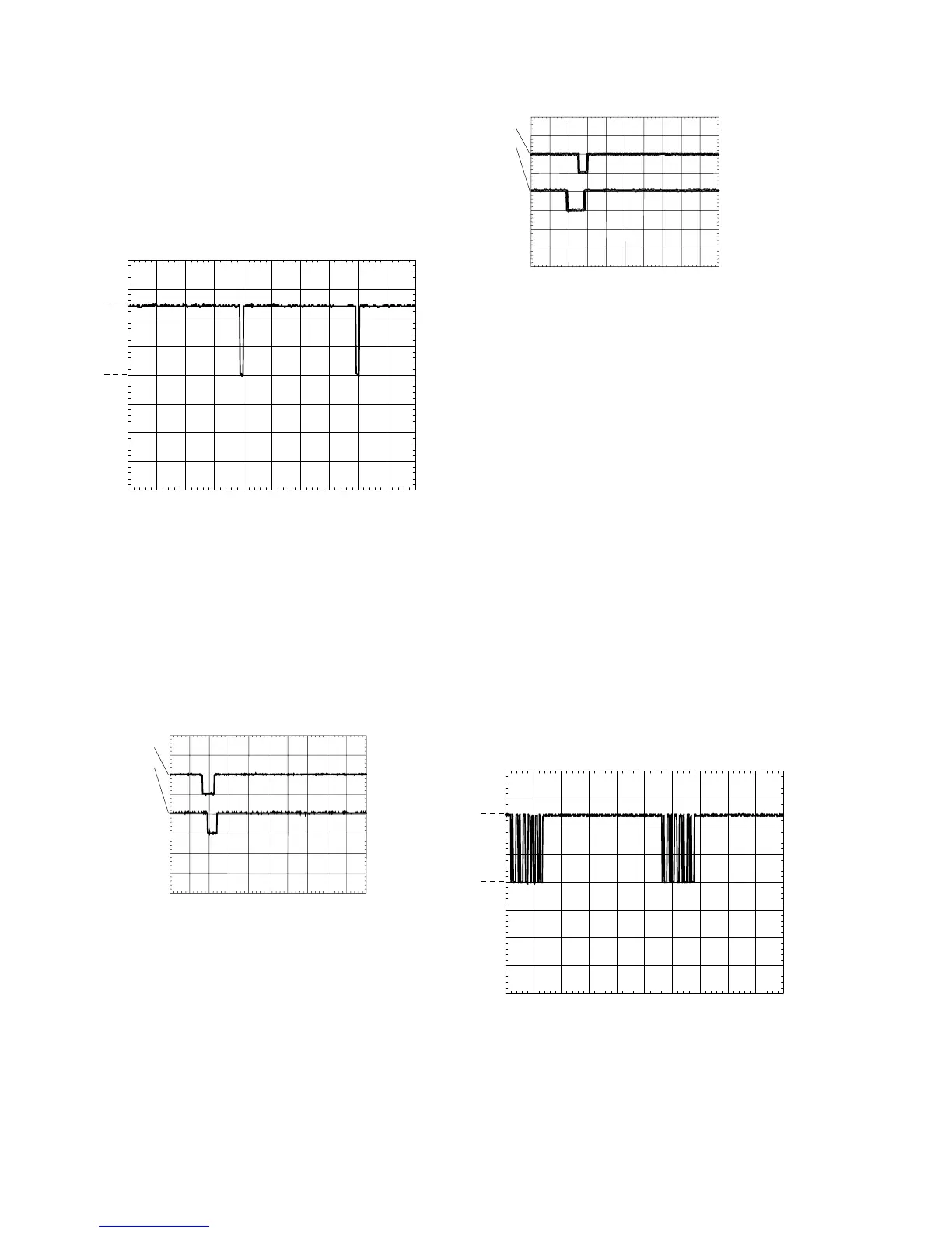
Key matrix lines
The lines connected to pins 18, 19, 20, 34, 35, 36 and 37 of the
display controller act as matrix scanners. Without a key pressed,
they maintain a low level. As soon as a key is pressed, the
scanning line connected to that key puts out a scanning signal,
which should look like the oscillogram below. This scanning signal
goes via the pressed key to I/O port 7 of the display controller
(pins 28 to 33). The display controller can now determine which
key has been pressed. Without a key pressed, pins 28 to 33 of
the display controller maintain a high level (+5V).
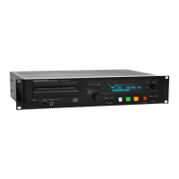
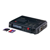
Easy jog knob
Rotary operation
The easy jog knob (SY26) incorporates a whole heap of user
control possibilities in just one knob. Without the knob being
operated, pin 1 and 3 of the knob (and thus pin 16 and 17 of the
display controller), maintain the +5V level. Turning the knob
clockwise briefly connects pin 1 to GND followed by pin 3.
The pulses created this way arrive at pin 16 and 17 of the
display controller. The first pulse to arrive tells the controller the
direction of the rotation. Counting the pulses reveals the
amount of rotation. Combining and decoding this information,
the display controller will execute the appropriate task.
Push button operation
This button connects to the key matrix lines and thus the
operation is identical to the ordinary keys. Without being
pressed, pin 4 of the easy jog maintains the low level, pin 5 the
high level. When pressed the scanning signal goes through the
closed contact of pins 4 and 5, and can be checked at both
pins.
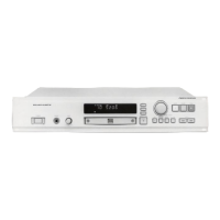
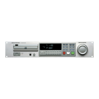
IR receiver - remote control
In the CDR631 the IR receiver ZY01 is mounted on the IR board.
In all versions the IR receiver connects to the display controller.
The signal coming from the receiver can be checked at pin 22 of
the display controller. This signal is normally high (+5V).
When the remote control is being operated, pulses mixed in with
the +5V can be measured. The oscillogram gives an indication of
how the signal looks like with the RC being operated.
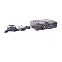
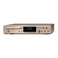
Figure 7-7 TURN ANTI-CLOCKWISE
Figure 7-6 TURN CLOCKWISE
Figure 7-5 KEY MATRIX SCAN LINE
Figure 7-8 IR RECEIVER SIGNAL
Turning the knob anti-clockwise briefly connects pin 3 to GND
followed by pin 1.
 Loading...