22
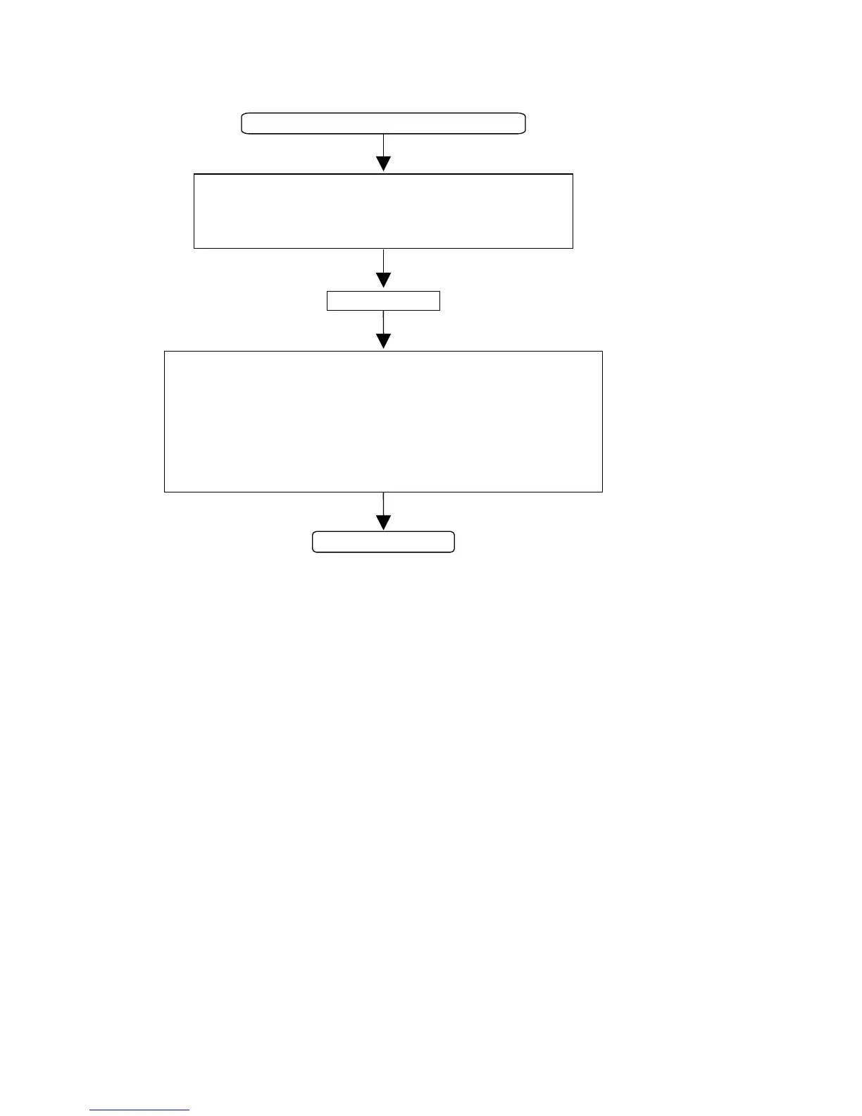
PRESS <PLAY>
LOAD SBC442 TEST CD (1kHz, -30dB) 4822 397 30155
CHECK:
·
Flex and wire connections
CL11 = 11.2896MHz at pin 2 conn. J601
·
·
+10V (QM01), -10V (QM02)
Kill transistors QN51, QN52, QN53, QN54
·
I
2
S signals at pin 5, pin 6, pin 8 conn. J601
·
CHECK:
DAC AOUTL +/-, DAC AOUTR +/- signals : 1kHz, 75mVpp
·
OPAMP pin1.Q603, pin1.Q604 signals : 1kHz, 180mVpp
·
DAC FILTER_L, DAC FILTER_R circuits (I/O board circuit diagram 5)
KILL voltage testpoint 1 : -8V during play
MUTE voltage : low during play
·
·
·
ANALOG OUT PATH OK
Figure 7-17
Troubleshooting analog-out path
7.2.3 Digital in/out paths
7.3 Headphone board
There is a cinch digital-in paths and an optical path taking the
digital signals pretty much straight to the DASP on the CDR
main board. The optical-out and the digital-out path take the
signal from the DASP on the CDR main board to their
respective output connectors on the I/O board.
The L and R analog signals coming from the analog output on
the I/O board pass an adjustable amplifier (opamp Q901) after
which they are passed on to the headphone connector. The
amplification is adjusted by means of a potentiometer
positioned at the front of the CDR player.
 Loading...