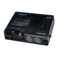
Do you have a question about the Marantz cp430 and is the answer not in the manual?
| Motor | DC Servo Motor |
|---|---|
| Microphone | Built-in |
| Tape Speed | 4.75 cm/s |
| Wow and Flutter | 0.08% (WRMS) |
| Inputs | Line In |
| Outputs | Line Out |
Details on the muting circuit for reducing pops noise during power on/off.
Explanation of auto play and auto rewind stop functions based on tape movement.
Description of the auto stop function that detects the end of the tape.
Function of the pitch control for adjusting tape speed during playback.
Procedure to adjust head azimuth for maximum VTVM reading and channel alignment.
Method to adjust tape speed using a test tape and frequency counter.
Procedure for measuring playback equalizer response with different tape types.
Steps to adjust playback level for left and right channels to specified voltage.
Procedure to adjust the level meter reading using a test tape.
Method for measuring playback noise volume on blank tape.
Steps to adjust the MPX filter for signal processing.
Adjusting frequency response and recording levels for Normal, CrO2, and Metal tapes.
Indicates specific alignment points on the printed circuit boards.
Detailed wiring diagrams illustrating the electrical connections of the unit.
Diagrams showing the physical location of chip components on various PCBs.
Block and level diagrams illustrating the signal flow and functional blocks.
Exploded view and parts list for front panel and general external components.
Exploded view and parts list for the main case and general internal components.
List of capacitors and resistors for the PK01 audio/main circuit board.
List of resistors and semiconductors for the PK01 circuit board.
List of various resistors and semiconductors used in the unit.
List of components for various circuit boards like PM02, PK02, PK03, PS01, PX01, PX02.
List of components for the PJO1 tape EQ and PM01 boards.
Details on wiring, assembly, and adjustment procedures for the unit.