Do you have a question about the Marantz DR6050 series and is the answer not in the manual?
| Type | CD Recorder |
|---|---|
| Dynamic Range | 96 dB |
| Analog Inputs | 2 x RCA |
| Digital Inputs | 1 x Coaxial, 1 x Optical |
| Digital Outputs | 1 x Coaxial, 1 x Optical |
| Disc Formats | CD-R, CD-RW |
| Recording Format | PCM |
| Frequency Response | 20Hz - 20kHz |
| Analog Outputs | RCA |
Procedure for ordering Marantz replacement parts via mail or fax.
Essential safety test for leakage current before customer return.
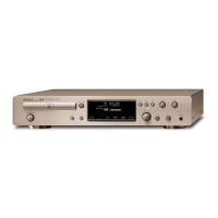
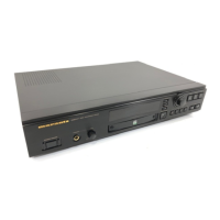
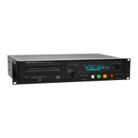
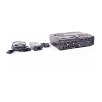
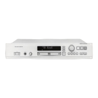
Overview of the DR6050 as a consumer CD recorder.
Steps to open the unit for internal access to PCBs.
Information on the CDR loader module (CDL4009/MAR770) and its parts.
Details on the power supply board and its functionality.
Details on the display board and its interface components.
Procedure for initializing the CD-R module after replacement.
Overall specifications including power, dimensions, and applicable discs.
Detailed audio performance metrics like S/N, THD, and dynamic range.
Crucial warnings about ESD sensitivity and handling precautions.
List of recommended ESD protection items and their part numbers.
Requirements for maintaining original condition and safety component identification.
Laser radiation warning and mandatory leakage current test procedure.
Practical tips for handling components and PCBs during service.
Visual guides for component handling, soldering, and precautions.
List of specific tools required for servicing with part numbers.
Explanation and function of the dealer mode.
Procedure and description of the dealer diagnostics test.
Necessary prerequisites for performing dealer diagnostics.
Flowchart and purpose of electrical service diagnostics.
Checking player ID and software versions.
Procedures for DRAM, Flash, and CODEC tests.
Tests to verify CD loader functionality.
Detailed explanation of the electrical diagnostics process.
Prerequisites for conducting electrical diagnostics.
Explanations of specific diagnostic tests (DRAM, Flash, CODEC, etc.).
Introduction to the mechanical diagnostics procedure.
Procedure for mechanical diagnostics without disassembly.
Prerequisites for performing mechanical diagnostics.
Details on focus, sledge, and tray control tests.
Procedure for erasing CD-RW discs using DC erase.
Flowchart for troubleshooting CDR module related issues.
Troubleshooting steps for issues with CD-DA disc playback.
Troubleshooting steps for CD-R disc recording problems.
Troubleshooting steps for CD-RW disc erasing issues.
Flowchart for troubleshooting the CD module itself.
Confirmation of successful CD module playback.
Comprehensive guide for diagnosing display board issues.
Block diagram illustrating the TMP87C874F display controller.
Detailed list and explanation of display controller pins.
Procedures for testing supply voltages, clock, and control signals.
Testing and measurement of display grid lines.
Testing and measurement of display segment lines.
Testing the FTD filament voltage for proper operation.
Testing the scan lines for the key matrix.
Testing the rotary and push button functions of the jog knob.
Testing the IR receiver's signal for remote control input.
Guide for diagnosing issues based on display output.
Diagnostic steps for issues related to key functions.
Diagnostic steps for problems with remote control input.
Detailed description of the switching power supply unit.
Detailed explanation of the MC44603 power supply controller IC.
Block diagram of the P816 power supply unit.
Pinout and connections for the MC44603 controller.
Detailed explanation of each pin's function on the MC44603.
Block diagram illustrating the MC44603 controller's internal architecture.
Step-by-step explanation of the power supply's start-up process.
Explanation of the power supply's operation during the regulation phase.
Diagram illustrating key signals during power supply regulation.
Visual representation of various power supply operational signals.
Detailed description of the P816 power supply circuit components.
Description of the power supply's input protection and EMI filter.
Explanation of the primary rectification and smoothing stages.
Description of the circuit responsible for start-up and Vcc supply.
Step-by-step guide for troubleshooting the power supply unit.
Overview of the CD main board and its primary functions.
Specifies the voltage inputs required by the CD main board.
Details on clock signals essential for CD board operation.
Description of the SAA7324 CD10 decoder and servo IC.
Block diagram of the SAA7324 CD10 integrated circuit.
Pinout diagram and identification for the SAA7324 IC.
Description of TDA7073A power drivers used for servo functions.
Voltage measurements for the TDA7073A power drivers.
Description of the BA6856FP IC for turntable motor control.
Logic table detailing motor controller inputs and outputs.
Voltage level specifications for hall element inputs.
Explanation of the tray control system and its operation.
Measurement procedures for tray control signals.
Explanation of the high-frequency signal path circuitry.
Settings for DC measurements within the HF path.
Data on the transfer characteristics of the HF signal path.
Configuration settings for the HF detector function.
Description of the UDA1320 DAC and I2S audio interface.
Explanation of I2S signals: CLOCK, WORD-SELECT, DATA.
Procedures for measuring DAC output signals and mute function.
Instructions for safely removing specific cables from the loader PCB.
Wiring specifications for the WY01 connector on the CDR main board.
Wiring specifications for the WY02 connector on the CDR main board.
Wiring specifications for the WY03 connector on the CDR main board.
Wiring specifications for the WY04 connector on the CDR main board.
Overall block diagram of the CDR main board components and connections.
Schematic and parts layout for the display assembly.
Schematic and parts layout for the PY16 board.
Schematic and parts layout for the PY26 board.
Schematic and parts layout for the PY36 board.
Detailed schematic diagram for the P816 power supply PCB.
Diagram showing the physical placement of parts on the PY16 board.
Diagram showing the physical placement of parts on the PY26 board.
Diagram showing the physical placement of parts on the PY36 board.
Diagram showing the physical placement of parts on the PY46 board.
Visual representation of the unit's assembly with numbered parts.
Comprehensive list of all parts with numbers, descriptions, and MJI codes.
Explanation of codes used for common resistors and capacitors.
List of commonly used resistors, their values, and codes.
List of commonly used capacitors, their values, and codes.
Safety warning regarding component substitution and risks.
Detailed list of electrical components for the P816 power board.
List of common capacitors specific to the P816 board.
List of common resistors specific to the P816 board.
List of semiconductor components used on the P816 board.
List of electrical components for the PP16 rear panel board.
List of capacitors specific to the PP16 board.
List of common resistors specific to the PP16 board.
List of semiconductor components used on the PP16 board.
List of electrical components for the PY26 key circuit board.
List of electrical components for the PY36 rotary encoder board.
List of electrical components for the PY46 LED circuit board.