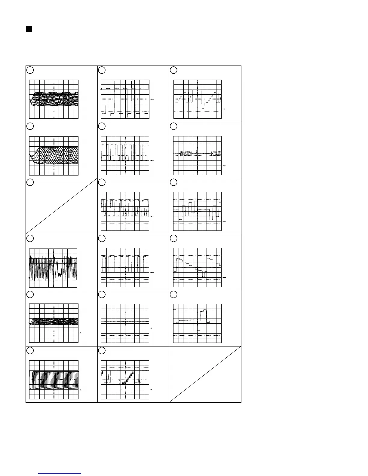
WAVEFORMS
Note : The encircled numbers denote measuring point in the schematic diagram.
Measurement condition : No. 1 to 4 and 6 to 11 : MJK1, Title 1-chp 1 or TDV-540, Title 2-chp1
No. 5 : CD, ABEX-784 Track 1 or PHILIPS SBC 429 Track1
No. 12 to 14 : MJK1, Title 1-chp 4 or TDV-540, Title 2-chp1
No. 15 to 17 : MJK1, Title 1-chp 5 or TDV-540, Title 2-chp1
1
Foot of R169 (RF)
V: 100mV/div. H: 0.2µsec/div.
2
TP2 (RFO)
V: 500mV/div. H: 0.1µsec/div.
3
4
TP3 (Tracking Error)
(AI-Inner Tracking Off)
V: 500mV/div. H: 2msec/div.
5
IC2 - pin 39 (EFM before slice)
V: 1V/div. H: 1µsec/div.
6
IC2 - pin 1 (EFM)
V: 1V/div. H: 0.2µsec/div.
7
IC3 - pin 41 (REGB)
V: 1V/div. H: 5msec/div.
8
Foot of R261 (FPWM)
V: 1V/div. H: 5msec/div.
9
Foot of R262 (VPWM)
V: 1V/div. H: 5msec/div.
10
Foot of R263 (PPWM)
V: 1V/div. H: 5msec/div.
11
Foot of R264 (RPWM)
V: 1V/div. H: 5msec/div.
12
IC18 - pin 45
(Composite Video output)
V: 2V/div. H: 1msec/div.
13
IC18 - pin 39 (Y output)
V: 0.2V/div. H: 5msec/div.
14
IC18 - pin 36 (C output)
V: 0.2V/div. H: 5msec/div.
15
IC18 - pin 45 (CB output when
selecting color difference output)
V: 0.2V/div. H: 5msec/div.
16
IC18 - pin 39 (Y output when
selecting color difference output)
V: 0.2V/div. H: 5msec/div.
17
IC18 - pin 36 (CR output when
selecting color difference output)
V: 2V/div. H: 5msec/div.
GND
GND
GND
GND
GND
GND
GND
GND
GND
GND
GND
GND
3-9