54
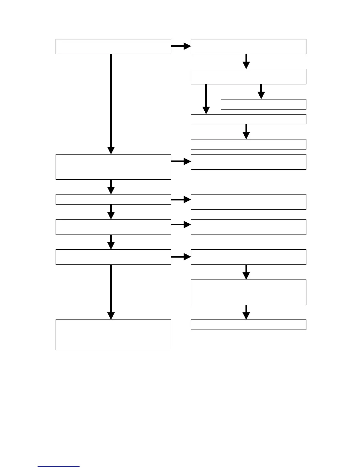
4.2 Check the HDMI driver.
NG
OK
NG OK
OK
NG
NG
OK
OK
NG
OK
OK
OK
OK
NG
OK
Are the VS+3.3V and HDP+3.3V voltage
lines of QT01 normal?
Are input digital signals normal?
HDY(0-9), HDC(0-9), HDDE, HDHSYNC,
HDVSYNC and HDVCLK
Is the reset signal (VRST_4) of QT01 H?
Is the IIC waveform of QT01 normal?
SDA1 and SCL1
Is the picture of the television inputted
by HDMI normal?
Finish
(Of course, there needs to be no problem
in video and audio output signal.
And the audio also checks HD_SPDIF.)
Check the soldering of QT01, QT05,
QW81 and LT01-LT04.
Check the input voltage of QT05 and QW81.
Replace QT05 or QW81.
Check the soldering of JW02 and JK02.
Refer to “1. POWER SUPPLY PCB”.
Check the soldering of QT01, RT01-RT03
and RT14-RT19.
Check the soldering CT03, JW02, JK02
and QU01 (25pin).
Check the soldering of QT01, RT11, RT12,
CT04 and CT05.
Check the soldering of JT01, LT06-LT09
and RT31-RT38.
Check the soldering of QT03, LT05, QT02,
RT22-RT26, RT30 and circumference
components.
Replace QT01.